System for image-guided endovascular prosthesis and method for using same

a technology of endovascular prosthesis and imageguided technology, which is applied in the field of system for can solve the problems of ineffective and potentially dangerous therapy, low information currently available, and high incidence of spinal cord damage, and achieve accurate tracking, accurate placement of endovascular prosthesis, and substantial reduction of the dimension of the delivery system

a technology of endovascular prosthesis and imageguided technology, which is applied in the field of system for can solve the problems of ineffective and potentially dangerous therapy, low information currently available, and high incidence of spinal cord damage, and achieve accurate tracking, accurate placement of endovascular prosthesis, and substantial reduction of the dimension of the delivery system

US20080015677A1Active Publication Date: 2008-01-17PHILIPS ELECTRONICS LTD +1

Image

  • System for image-guided endovascular prosthesis and method for using same
  • System for image-guided endovascular prosthesis and method for using same
  • System for image-guided endovascular prosthesis and method for using same

Examples


Embodiment Construction

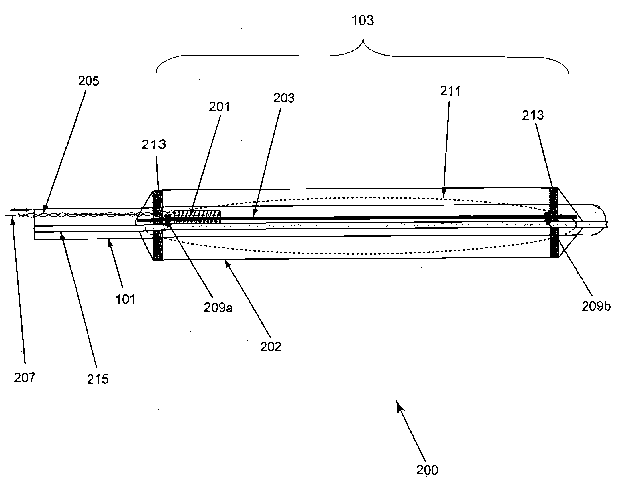
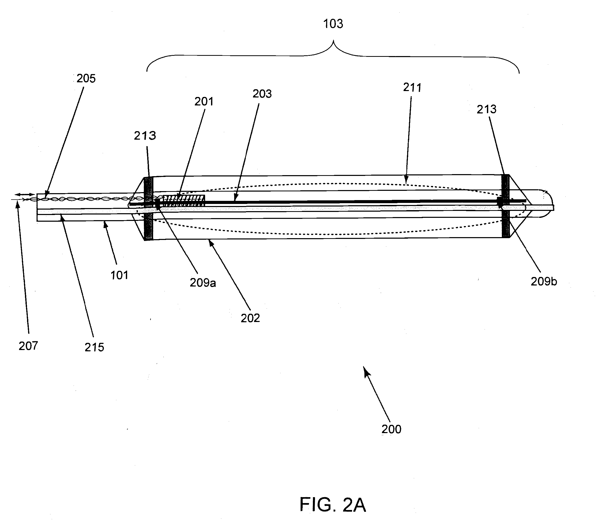
[0036] In some embodiments, the system and method of the invention enables tracking of endovascular prostheses and / or patient structures using electromagnetic (EM) or other tracking systems that track one or more position indicating elements. In some embodiments, the invention also enables determination of multiple locations within an endovascular prosthesis through the use of trackable position indicating elements that are selectively movable within the body of an endovascular prosthesis.

[0037] In some embodiments, the invention utilizes tracking systems to obtain position sensor space data regarding endovascular prostheses and instrumentation used therewith. This position sensor space data may enable enhanced / accurate placement, deployment, and modification of endovascular prostheses as well as providing other features. For example, in some embodiments, use of a tracking system enables dynamic referencing during placement and deployment of an endovascular prosthesis which may ena...


PUM


Abstract

The invention provides systems and methods for obtaining position sensor space data regarding an endovascular prosthesis within an anatomical region of a patient, wherein at least one position indicating element is movable within an endovascular prosthesis is tracked by a tracking system. A guidance portion of the endovascular prosthesis constrains movement of position indicating elements within the endovascular prosthesis.

Description

RELATED APPLICATIONS [0001] This application claims priority to U.S. Provisional Patent Application Ser. No. 60 / 812,121, filed Jun. 9, 2006, which is hereby incorporated by reference herein in its entirety.STATEMENT OF GOVERNMENT RIGHTS [0002] The Government of the United States of America may have certain rights in the invention disclosed and claimed below.FIELD OF THE INVENTION [0003] This invention relates to a system for an image-guided endovascular prosthesis placement device that includes position sensing elements movable between two or more positions relative to an endovascular prosthesis as well as a method for using the image-guided endovascular prosthesis placement device. BACKGROUND OF THE INVENTION [0004] Stents, grafts, covered stents, vascular endoprostheses, struts or other endovascular devices of various shapes, sizes, and materials are generally used as therapy for minimally invasive treatment of various conditions such as, for example, vascular aneurysms (especiall...

Claims


Application Information

Patent Timeline
17 Jan 2008
Publication
US20080015677A1
IPC
A61F2/06; A61F2/82
CPC
A61B5/06; A61F2250/0002; A61F2/95; A61F2/82
Inventors
GLOSSOP, NEIL DAVID; WOOD, BRADFORD JOHNS