Fired heater

a heater and heater technology, applied in the field of fired heaters, can solve the problems of refineries that cannot process the required throughput through furnaces, the ability of refineries to push their heaters to the limit, and the cracking of hydrocarbons, so as to achieve the effect of reducing the buildup of coke in the tubes

Active Publication Date: 2008-05-01
GARG ASHUTOSH
View PDF13 Cites 6 Cited by
  • Summary
  • Abstract
  • Description
  • Claims
  • Application Information

AI Technical Summary

Benefits of technology

[0010]It is an object of this invention to provide heaters which minimize coke build up in tubes.

Problems solved by technology

As these hydrocarbon fluids are heated, some of the hydrocarbons start cracking and getting converted into carbon due to high film temperature.
A major limitation in the ability of refineries to push their heaters to the limit is linked to coke formation in the radiant section tubes.
With excessive coke formation, the refiners cannot process the required throughput through the furnace and have to shutdown to clean the heaters prematurely.
Heating the oil molecules to high temperature causes ‘cracking’ with the subsequent formation of coke on the inner surface of the tubes.
It insulates the tubes and impedes the heat transfer.
Firing the heater harder creates inevitable problems.
The fired heater operation not only becomes inefficient (due to higher beat losses in the flue gases resulting from the increased heat input), but also potentially dangerous.
The danger lies in the excessively high temperatures that the tubes may reach, which can cause rapid scaling of the metal and possible rupture of the tube.
Tube metals differ according to the type of process and severity of duty but they can all suffer damage due to overheating Further, as the heater is fired harder, the risk of flame impingement on the tubes also increases.
These shutdowns cost refineries a lot of down time and money.

Method used


Image

  • Fired heater
  • Fired heater
  • Fired heater

Examples


Embodiment Construction

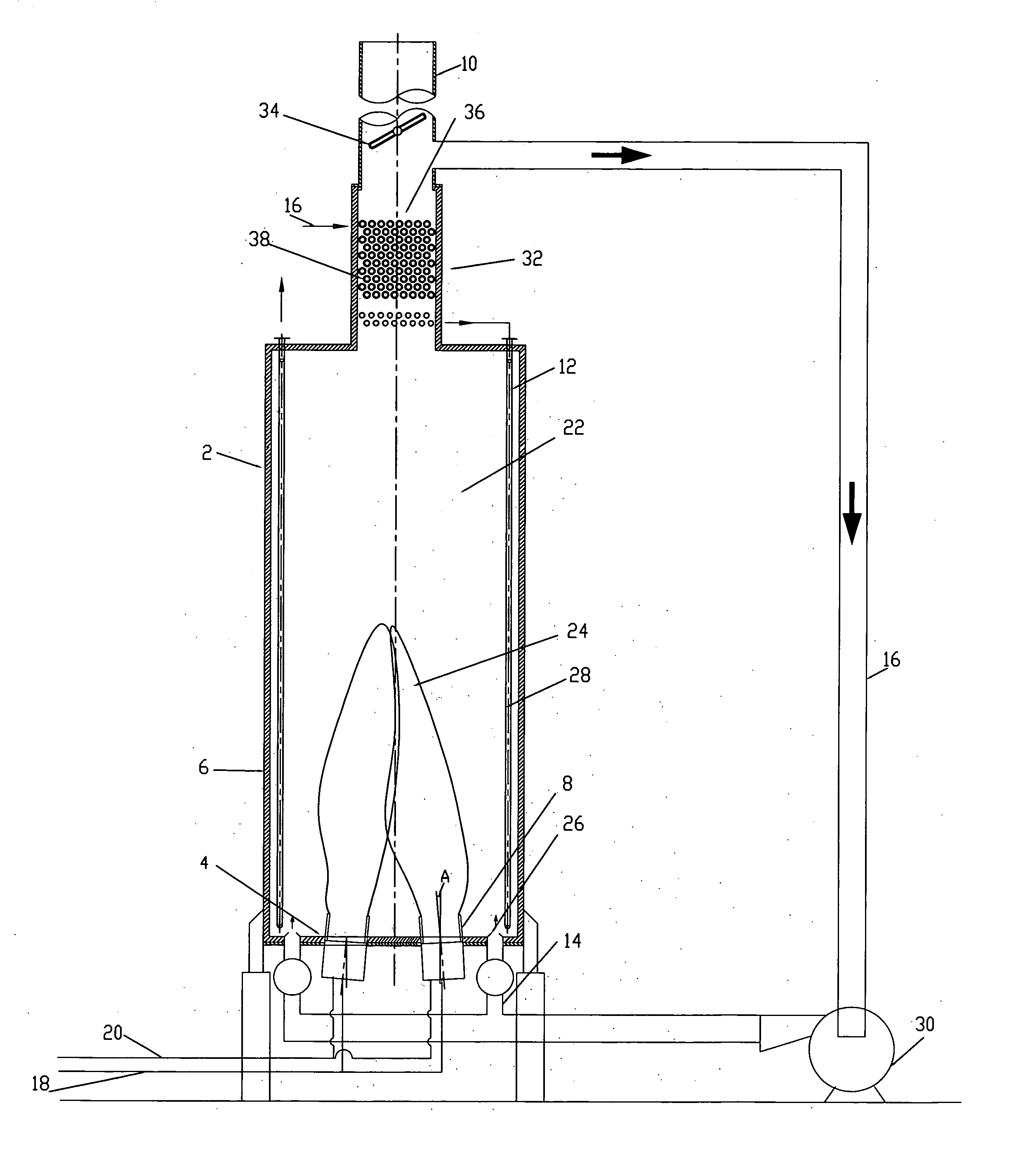
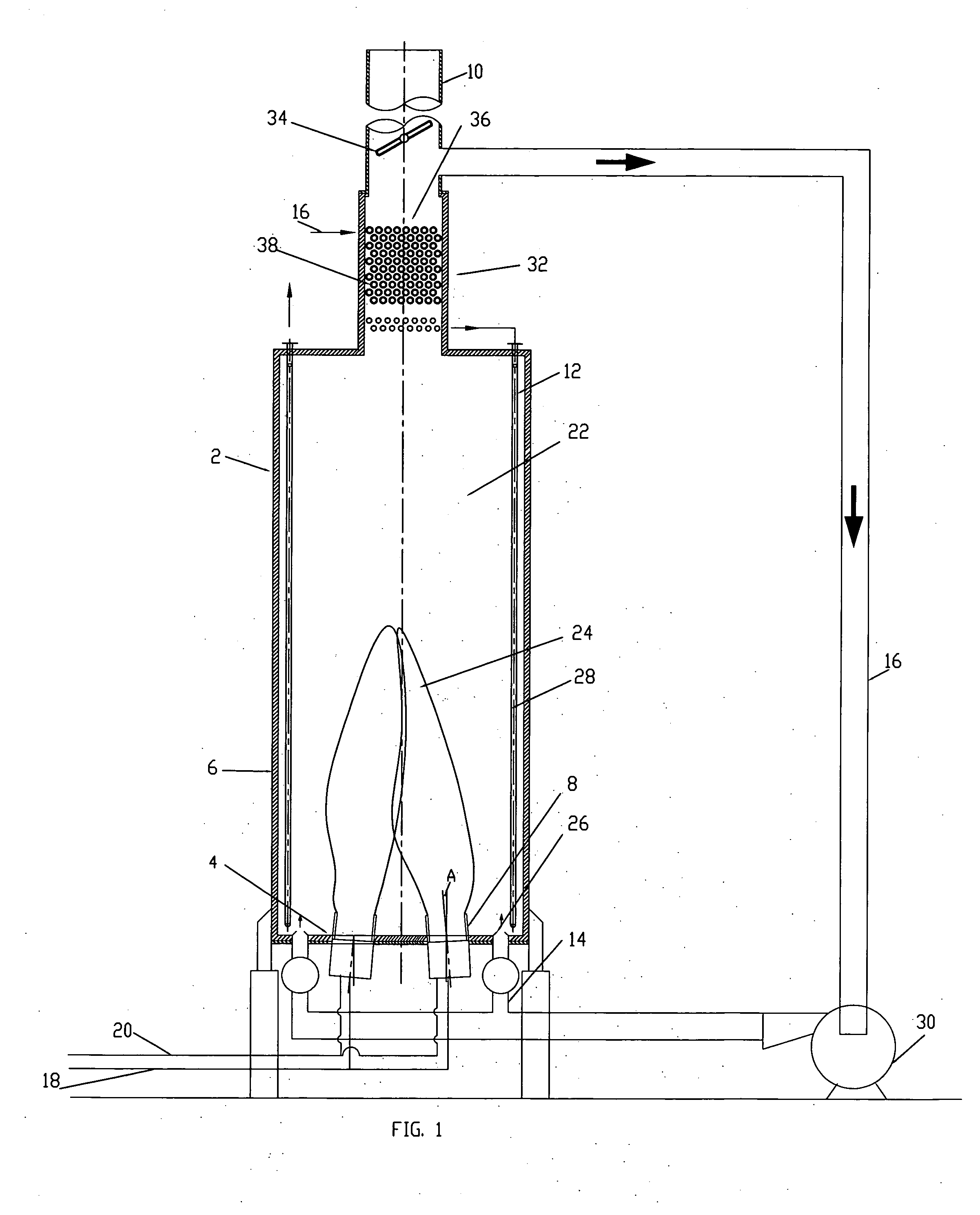
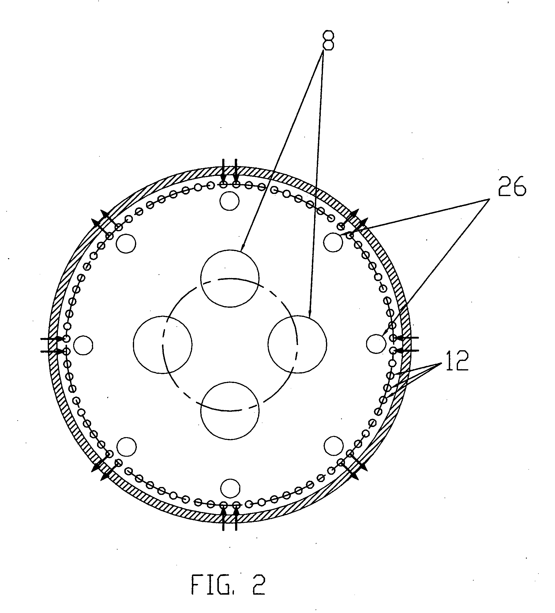
[0026]In one embodiment of my invention, there is provided a method of operating a fired heater to heat a hydrocarbon feedstock flowing though a tubing positioned along a periphery of the heater. The heater includes one or more burners positioned at a spaced apart location inwardly from the tubing. The method is carried out by introducing a plurality of relatively cool gas streams between the burners and the tubing to moderate burner heat flux on the tubing. The method is expected to provide good benefits when heating heavy oils, for example, petroleum oils or petroleum residuum, to high outlet temperatures, for example, in the range of 750 to 950 F.

[0027]In the preferred embodiment, the burners produce flue gases. These flue gases are cooled and the relatively cool gas streams are formed from a portion of the cooled flue gases. In the range of 15% to 60% of the flue gases produced by the at least one burner can be used in this manner. The streams are preferably introduced into the ...


PUM


Abstract

Two improvements for heaters are disclosed which can be implemented as either apparatus or method. First is a novel flue gas injection system. Second is a novel burner configuration. The improvements can be used alone or together. In the flue gas injection system, flue gas is injected between the burners and the tubes to reduce heat flux on the tubes and shift part of the heat duty from the radiant to the convective section. These approaches work toward increasing the capacity of heaters where we can increase the firing rate in the heater and still keep the tube metal temperature and radiant fluxes within acceptable limits.

Description

FIELD OF THE INVENTION[0001]In one aspect, this invention relates to fired heaters used in the petrochemical and petroleum refining industries for heating charge stock. In another aspect, this invention relates to methods for operating fired heaters to provide an increased throughput of charge stock and / or a reduced coking rate.BACKGROUND OF THE INVENTION[0002]Fired heaters are the most important and largest equipment in any refinery. Refineries always want to push their heaters to the limit. In most of the fired heaters used in the refining and petrochemicals industry, hydrocarbons are heated inside the tubes. As these hydrocarbon fluids are heated, some of the hydrocarbons start cracking and getting converted into carbon due to high film temperature. A major limitation in the ability of refineries to push their heaters to the limit is linked to coke formation in the radiant section tubes. With excessive coke formation, the refiners cannot process the required throughput through th...

Claims


Application Information

Patent Timeline
Patent Type & Authority Applications(United States)
IPC IPC(8): F22B7/00
CPCF22B21/343F23C9/08F23C5/14
Inventor GARG, ASHUTOSH
Owner GARG ASHUTOSH
Why Eureka
Try Eureka