Tamp for concave resurfacing prosthesis

a prosthesis and concave technology, applied in the field of implants, can solve the problems of subcondylar plate damage or missing, premature wear of the articulating surface and loss of fixation, and difficulty in achieving fixation of the revision glenoid componen

Inactive Publication Date: 2008-05-08
DEPUY PROD INC
View PDF16 Cites 20 Cited by
  • Summary
  • Abstract
  • Description
  • Claims
  • Application Information

AI Technical Summary

Benefits of technology

[0035] Another technical advantage of the present invention includes the ability to provide for an effective glenoid prosthesis when the cortical walls of the glenoid vault are severely damaged. For example, according to one aspect of the present invention, the prosthesis includes metal walls that substitute for a portion of the cortical walls of the glenoid vault.
[0036] Yet another technical advantage of the present invention includes the ability to provide for a glenoid prosthesis when the cancellous bone in the glenoid vault has voids. For example, according to one aspect of the present invention, the glenoid vault is cleaned and removed of cancellous bone. The glenoid vault then is filled with a combination of bone graft and / or cement, and the prosthesis of the present invention that fills a substantial portion of the glenoid vault is implanted. Thus, the present invention provides for a glenoid prosthesis that is suitable to be used where the glenoid vault includes voids of cancellous bone.

Problems solved by technology

However, the current trend is to use the cements to a lesser extent because of their tendency to lose adhesive properties over time and the possibility that the cement contributes to wear debris within a joint.
Unfortunately, for a variety of reasons, an implant, for example, a shoulder prosthesis, may occasionally need to be revised or have the old implant surgically removed and a new implant positioned where the prior implant had been removed.
Primary failure modes are premature wear of the articulating surface and loss of fixation.
When a failed glenoid component is removed, often the subcondylar plate is damaged or missing along with a large defect in the cancellous bone of the glenoid vault of the scapula.
Fixation of a revision glenoid component can be difficult to achieve with a resulting limited bone stock remaining on the glenoid vault of the scapula after the revision surgery has been performed.
Attempts to provide for a adequate revision glenoid component for revision surgery have met with less than optimal results.
Not only is the support at the cortical bone areas 8 very limited, the support between the cortical bone maybe full of voids 9 which further reduce the ability of the standard glenoid prosthesis to be properly supported.
The failed glenoid component resulted in a void in the subcondylar plate and the underlying cancellous bone bed.
As can be shown in FIGS. 1 through 9, in many cases the subcondylar plate defects and the underlying cancellous bone defects increase the difficulty in achieving appropriate prosthesis fixation and support.

Method used


Image

  • Tamp for concave resurfacing prosthesis
  • Tamp for concave resurfacing prosthesis
  • Tamp for concave resurfacing prosthesis

Examples


Embodiment Construction

[0072] Embodiments of the present invention and the advantages thereof are best understood by referring to the following descriptions and drawings, wherein like numerals are used for like and corresponding parts of the drawings.

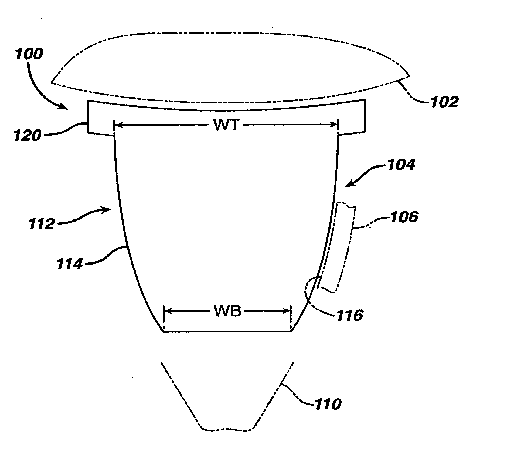
[0073] According to the present invention referring now to FIGS. 10 and 11, a glenoid component 100 for use with a prosthesis humeral component 102 for use in shoulder arthroplasty is shown. The glenoid component 100 is fitted at least partially into a cavity 104 formed in the glenoid vault 106 of the scapula 110. The glenoid component 100 includes a body 112 having a stem portion 114 for inserting at least partially into the cavity 104 formed in the glenoid vault 106. The stem portion 114 cooperates with the interior wall 116 of the cavity 104 formed in the glenoid vault 106. The body 112 also includes a bearing portion 120 for articulating cooperation with the prosthetic humeral component 102.

[0074] The glenoid component 100 may be made of any suitable du...


PUM

PropertyMeasurementUnit
diameteraaaaaaaaaa
lengthaaaaaaaaaa
shapeaaaaaaaaaa

Abstract

A tamp for use in forming grafting material into a cavity in the glenoid vault to prepare the vault for a glenoid component for performing shoulder arthroplasty is provided. The tamp includes a body and a forming portion. The forming portion extends in a first direction from the body. The forming portion including a surface thereof shaped to receive the glenoid component.

Description

CROSS REFERENCE TO RELATED APPLICATIONS [0001] This application is a Divisional Patent Application of Utility Patent Application Attorney Docket No. DEP0575USNP, U.S. patent application Ser. No. 10 / 259,045 titled “CONCAVE RESURFACING PROSTHESIS” filed Sep. 27, 2002. This application claims priority of Utility Patent Application Attorney Docket No. DEP0575USNP, U.S. patent application Ser. No. 10 / 259,045 titled “CONCAVE RESURFACING PROSTHESIS” filed Sep. 27, 2002. U.S. patent application Ser. No. 10 / 259,045 is hereby incorporated by reference herein in its entirety.TECHNICAL FIELD OF THE INVENTION [0002] The present invention relates generally to the field of orthopaedics, and more particularly, to an implant for use in arthroplasty. BACKGROUND OF THE INVENTION [0003] The invention relates to implantable articles and methods for manufacturing such articles. More particularly the invention relates to a bone prosthesis and a process from manufacturing the same. [0004] There are known t...

Claims


Application Information

Patent Timeline
Patent Type & Authority Applications(United States)
IPC IPC(8): A61F5/00A61F2/40A61B17/16A61B17/17A61B17/86A61B19/00A61F2/00A61F2/28A61F2/30A61F2/46
CPCA61B17/1684A61B2017/1778A61B2017/1602A61B2019/304A61F2/30734A61F2/30749A61F2/30767A61F2/40A61F2/4081A61F2/4601A61F2/4637A61F2/4675A61F2002/2835A61F2002/30125A61F2002/3021A61F2002/30217A61F2002/30326A61F2002/30408A61F2002/30448A61F2002/30502A61F2002/30507A61F2002/30512A61F2002/30574A61F2002/30579A61F2002/30594A61F2002/30598A61F2002/30604A61F2002/30616A61F2002/3069A61F2002/30736A61F2002/30738A61F2002/30794A61F2002/30828A61F2002/30878A61F2002/30884A61F2002/30891A61F2002/30892A61F2002/30957A61F2002/4018A61F2002/4602A61F2002/4623A61F2002/4631A61F2002/4681A61F2220/0008A61F2220/0025A61F2220/005A61F2230/0008A61F2230/0067A61F2250/0037A61F2250/006A61F2310/00017A61F2310/00023A61F2310/00029A61F2310/00395A61F2310/00401A61F2310/00407A61F2310/00413A61B17/86A61B2090/034A61B17/1778A61F2002/305A61F2002/3079A61F2/4603
Inventor MARONEY, BRIAN JOHNWILLIAMS, GERALD ROSS
Owner DEPUY PROD INC
Why Eureka
Try Eureka