Systems and methods for semiconductor structure processing using multiple laser beam spots

a laser beam and semiconductor technology, applied in semiconductor/solid-state device testing/measurement, semiconductor/integrated circuit details, instruments, etc., can solve problems such as difficult to achieve large throughput gains, link banks may not be straight rows, and link runs may not be processed with continuous motion

a laser beam and semiconductor technology, applied in semiconductor/solid-state device testing/measurement, semiconductor/integrated circuit details, instruments, etc., can solve problems such as difficult to achieve large throughput gains, link banks may not be straight rows, and link runs may not be processed with continuous motion

US20080124816A1Inactive Publication Date: 2008-05-29ELECTRO SCI IND INC

Image

  • Systems and methods for semiconductor structure processing using multiple laser beam spots
  • Systems and methods for semiconductor structure processing using multiple laser beam spots
  • Systems and methods for semiconductor structure processing using multiple laser beam spots

Examples


Embodiment Construction

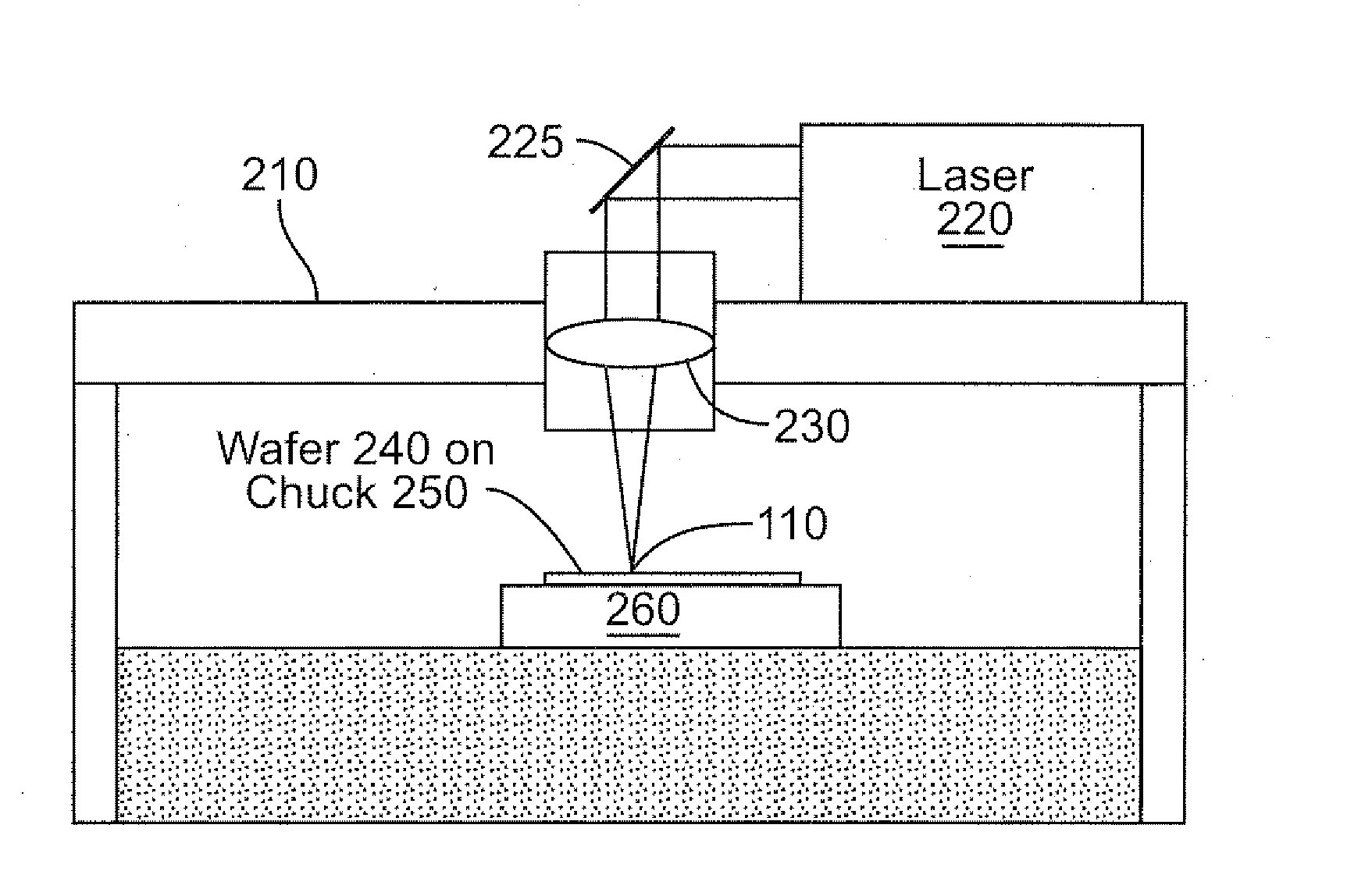
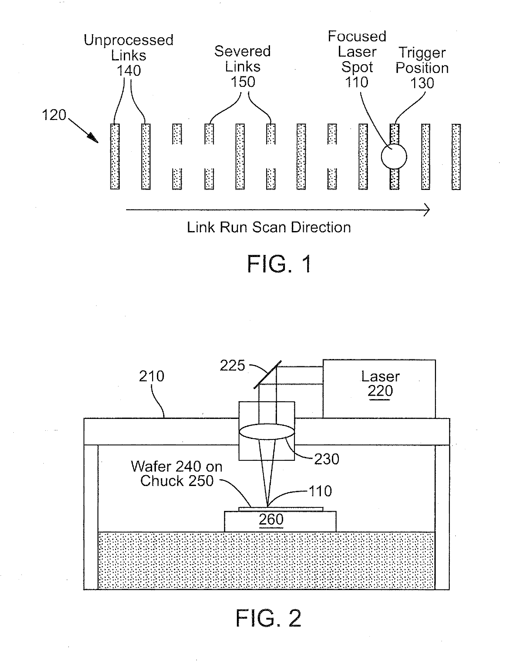
[0040]With reference to the above-listed drawings, this section describes particular embodiments and their detailed construction and operation. The principles, methods, and systems disclosed below have general applicability for processing any structure on or within a semiconductor substrate using laser radiation for any purpose. While the examples and embodiments that follow are described in the context in which those structures are laser-severable links on or within an IC (e.g., memory device, logic device, optical or optoelectronic device including LEDs, and microwave or RF devices), other structures besides laser-severable links can be processed in the same or similar manner, and the teachings set forth herein are equally applicable to the laser processing of other types of structures, such as electrical structures that become conductive as a result of laser radiation, other electrical structures, optical or electro-optical structures, and mechanical or electro-mechanical structu...


PUM

PropertyMeasurementUnit
Poweraaaaaaaaaa
Sizeaaaaaaaaaa
Electrical conductoraaaaaaaaaa

Abstract

Methods and systems selectively irradiate structures on or within a semiconductor substrate using multiple laser beams. The structures may be laser-severable conductive links, and the purpose of the irradiation may be to sever selected links.

Description

RELATED APPLICATIONS[0001]This application is a continuation-in-part of each of the following three U.S. patent applications: (1) Ser. No. 11 / 051,265, filed Feb. 4, 2005, entitled “Semiconductor Structure Processing Using Multiple Laterally Spaced Laser Beam Spots With On-Axis Offset,” which claims priority to U.S. Provisional Application No. 60 / 580,917, filed Jun. 18, 2004, entitled “Multiple-Beam Semiconductor Link Processing”; (2) Ser. No. 11 / 481,562, filed Jul. 5, 2006, entitled “Systems and Methods for Alignment of Laser Beam(s) for Semiconductor Link Processing,” which is a continuation-in-part of the above-referenced U.S. patent application Ser. No. 11 / 051,265; and (3) Ser. No. 11 / 499,394, filed Aug. 3, 2006, entitled “Systems and Methods for Distinguishing Reflections of Multiple Laser Beams for Calibration for Semiconductor Link Processing,” which is also a continuation-in-part of the above-referenced U.S. patent application Ser. No. 11 / 051,265. All of the preceding applica...

Claims


Application Information

Patent Timeline
29 May 2008
Publication
US20080124816A1
IPC
H01L21/268; B23K26/16; H01L21/66
CPC
B23K26/041; B23K26/0613; B23K26/063; H01L23/5258; B23K26/0807; G11C17/14; G11C17/143; B23K26/067
Inventors
BRULAND, KELLY J.; SWARINGEN, STEPHEN N.