Pumping and Repairing Unit

a pumping and repairing unit technology, applied in the field of oil machinery, can solve the problems of reduced life time, insufficient traction force, and difficulty in pumping and repairing units being used for workover, and achieve the effects of increasing the traction force for workover, ensuring safety, and ensuring safety

Inactive Publication Date: 2008-06-05
JIN CHENGQUN
View PDF2 Cites 11 Cited by
  • Summary
  • Abstract
  • Description
  • Claims
  • Application Information

AI Technical Summary

Benefits of technology

[0005]It is an object of the present application to provide a pumping and repairing unit with a improved performance, which operates smoothly and reliably, and which is durable, and more convenient in usage and maintenance.
[0011]According to the present invention, the fixed pulley block is mounted to the supporting platform; the workover rope is fixed to the driving and braking device; and the other end of the workover rope is fixed to the supporting platform after it has wound around the fixed pulley block and the movable pulley block. The hanging connector is connected to the lower end of the movable pulley block. An oil pipe or the oil pumping polished rod is pulled up by the hanging connector so as to perform the workover. A traction force for workover is considerably increased by the improved fixed pulley block and movable pulley block. In addition, because the fixed pulley block corresponds to a well head, the oil pipe is not bended in workover so that the pumping and repairing unit is convenient in workover, thereby achieving pumping oil with high efficiency and safe workover. Especially, the pumping and repairing unit has a very complete and reliable function of workover. In workover, the oil pumping polished rod and oil pipe stand beside the main frame and is surrounded by canvas or nylon cloth so that a relatively sealed space is formed. Therefore, garbage is treated without environment pollution so that the workover is environment-friendly. Entire process of the workover is simple and convenient in operation. In addition, the driving device and the brake wheel disposed at the end of the driving device constitute the driving and braking device; the braking handle is disposed at the bottom of the main frame; and the brake wheel is controlled by the braking handle through the level. Therefore, components for transmitting power are protected by the brake wheel disposed at the end of the driving device in workover so as to prolong life time of the pumping and repairing unit.

Problems solved by technology

However, in the pumping and repairing unit with such a configuration, a hoisting barrel and a hoisting rope for workover offset far away from a center of a well so that an oil pipe is bended and a traction force is insufficient in the workover.
Therefore, it is difficult for the pumping and repairing unit to be used for workover.
In addition, since electrical brake is disposed only at a high-speed end of a power transmission of the pumping and repairing unit, transmission components of the power transmission are subject to huge impact during braking, resulting in reduced life time and deteriorated performance of the pumping and repairing unit.

Method used


Image

  • Pumping and Repairing Unit
  • Pumping and Repairing Unit
  • Pumping and Repairing Unit

Examples


Embodiment Construction

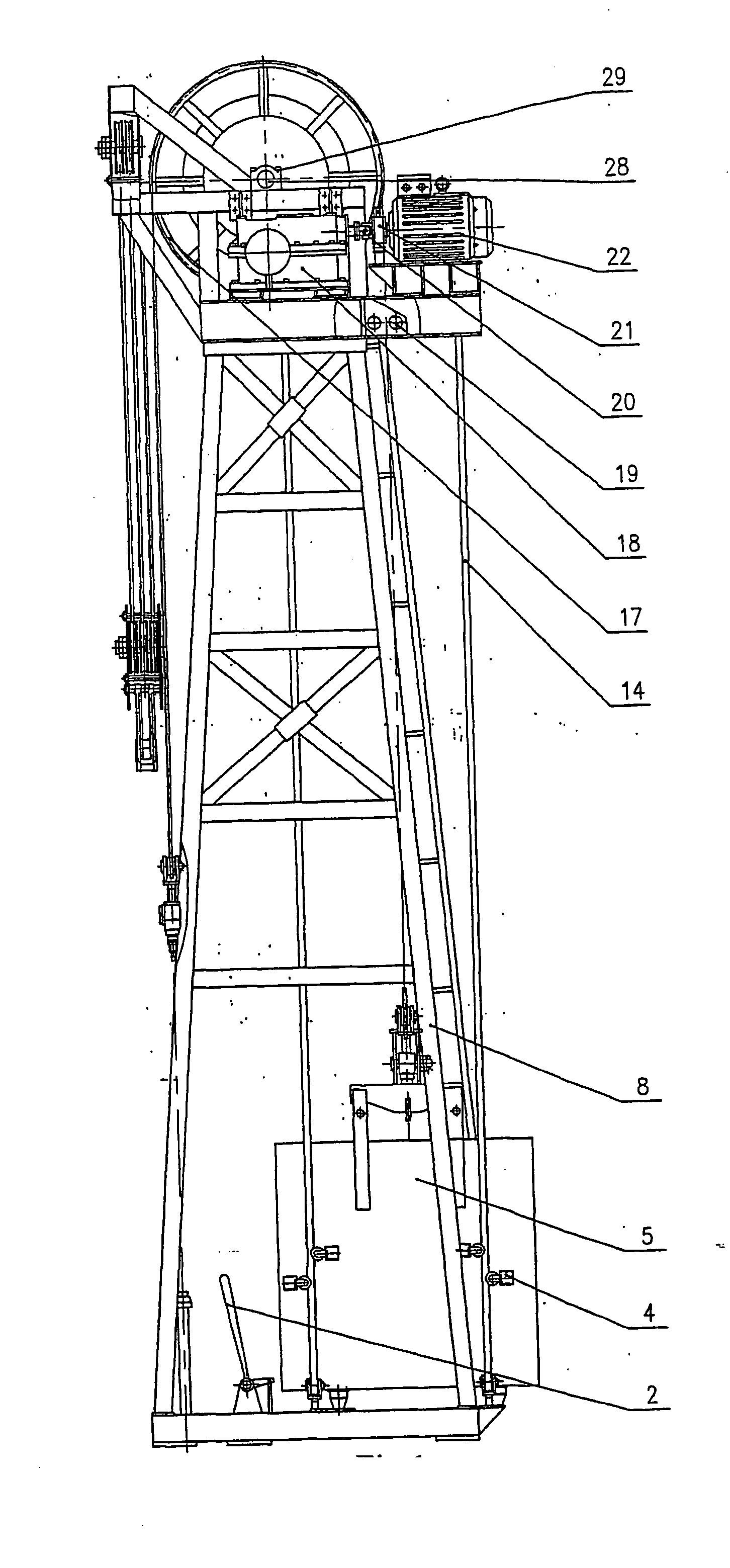
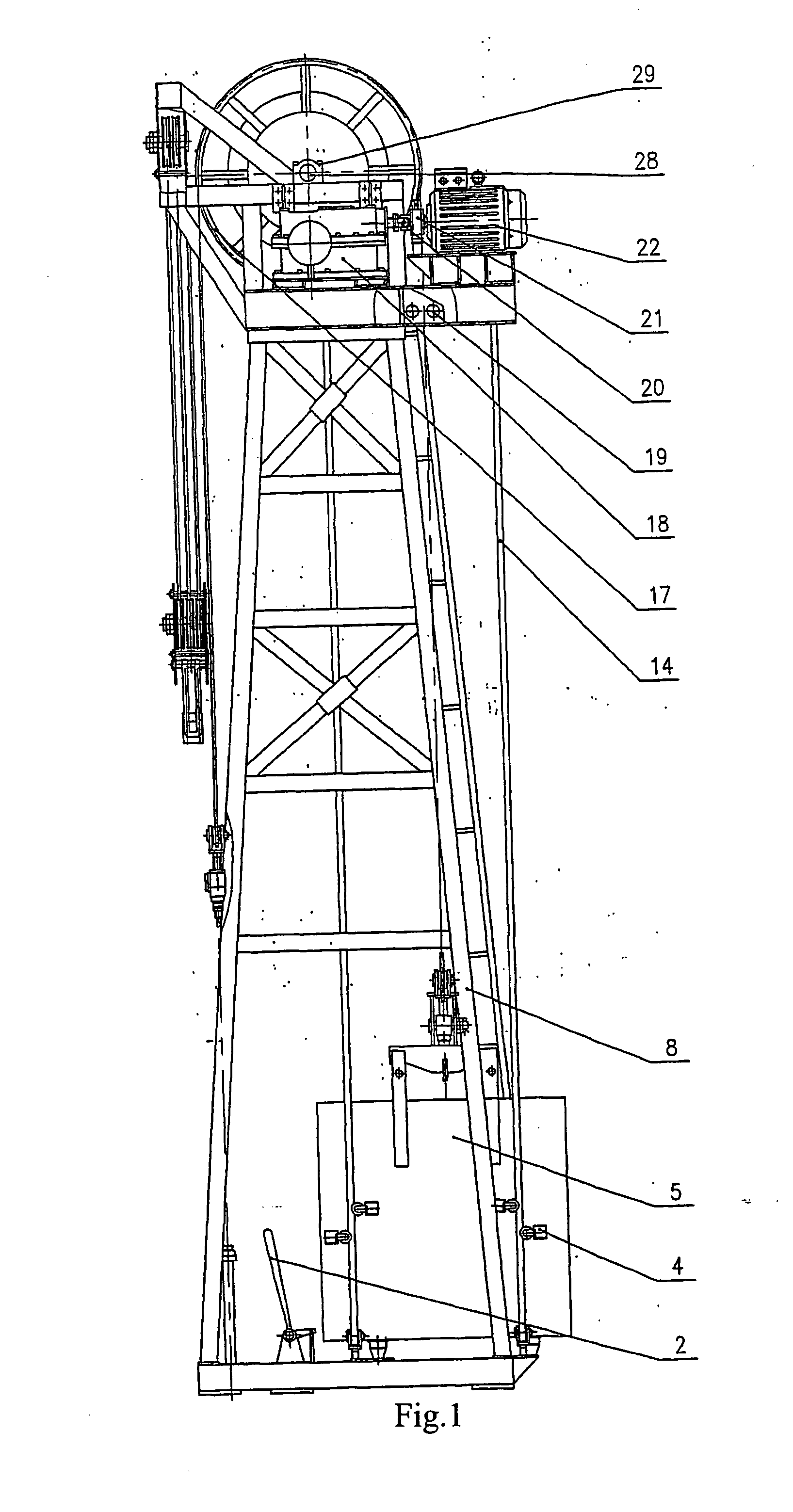
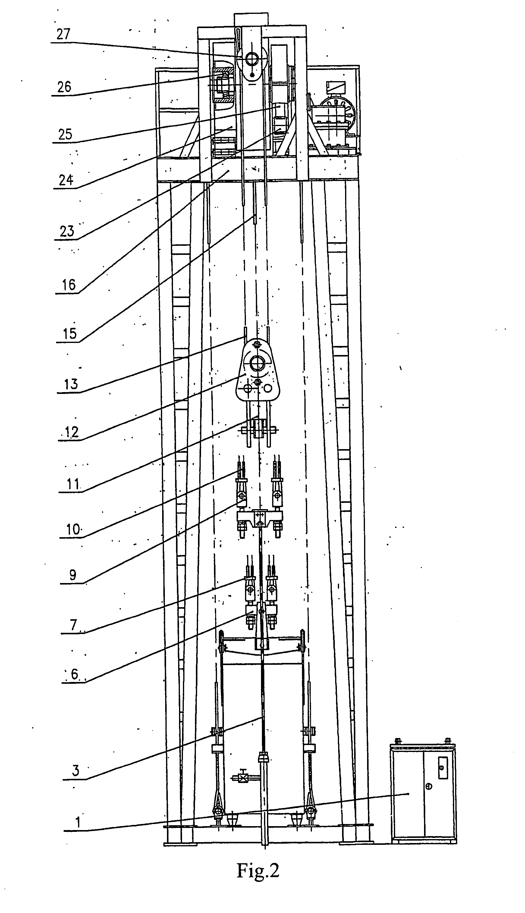
[0016]Referring to FIGS. 1 and 2, a pumping and repairing unit according to the present invention comprises an electrical control cabinet 1, a main frame 8, a supporting platform 16, a motor 22, an electrically operated brake 21, a coupling 20, a speed reducer 18, an oil pumping polished rod 3, a rope suspension device (or a polished rod eye) 9 for the oil pumping polished rod, an oil pumping polished rod rope 10, a balance weight case 5, a balance weight rope hanging device 6, a balance weight rope 7, a protection rope 15, a protection rope catching device 19, and a driving device. The supporting platform 16 is disposed on the main frame 8. The motor 22 is coupled with the speed reducer 18 through the electrically operated brake 21 and the coupling 20. The speed reducer 18 is coupled with the driving device. The oil pumping polished rod rope 10 has an end connected with the oil pumping polished rod 3 through the rope suspension device 9 and another end fixed to the driving device. ...


PUM


Abstract

The present invention relates to an oil machinery, and provides a pumping and repairing unit comprising: an electrical control cabinet, a main frame, a supporting platform, a motor, an electrically operated brake, a coupling, a speed reducer, an oil pumping polished rod, a polished rod eye for the oil pumping polished rod, an oil pumping polished rod rope, a balance weight case, a balance weight rope hanging device, a balance weight rope, a protection rope, a protection rope catching device, and a driving device. The oil pumping polished rod rope has an end connected with the oil pumping polished rod and another end fixed to the driving device. Each of the balance weight rope and the protection rope has an end connected with a balance weight rope hanging device, and another end fixed to the driving device. The driving device and a brake wheel disposed at an end of the driving device constitute a driving and braking device. A fixed pulley block is disposed at the supporting platform. A workover rope is fixed to the driving and braking device, and has another end which is fixed to the supporting platform after it has wound around the fixed pulley block and a movable pulley block. An elevator is coupled with a lower end of the movable pulley block. A braking handle is disposed at a bottom of the main frame, and the brake wheel is controlled by the braking handle. The pumping and repairing unit can achieve pumping oil with high efficiency and safe workover. Especially, the pumping and repairing unit has a complete and reliable function of workover, and does no harm to transmission components thereof and does not pollute environment during workover. Entire process of the workover is simple and convenient in operation.

Description

BACKGROUND OF THE INVENTION[0001]1. Field of the Invention[0002]The present invention relates to oil machinery, and particularly to a pumping and repairing unit which can be used for both oil pumping and well workover.[0003]2. Description of the Related Art[0004]Chinese Patent No. 200310100186.X discloses a pumping and repairing unit. The pumping and repairing unit comprises a head sheave shaft, a speed reducer, a larger gear, a small gear, an electric motor, a head sheave rope, a balance weight, a balance weight frame, guiding ropes, an oil pumping polished rod, a main frame, a supporting platform and a head sheave. A rope suspension device (or a polished rod eye) has an end connected with the polished rod, and another end connected with a periphery of a drum of the head sheave through a traction rope for the rope suspension device. The balance weight is fixed to the periphery of the drum of the head sheave through the balance weight frame, a rope hanging device, and a balance weig...

Claims


Application Information

Patent Timeline
Patent Type & Authority Applications(United States)
IPC IPC(8): E21B43/00
CPCE21B43/127E21B19/02
Inventor JIN, CHENGQUN
Owner JIN CHENGQUN
Why Eureka
Try Eureka