Camera shake determination device, printing apparatus and camera shake determination method

a technology of camera shake and determination device, which is applied in the field of detection of blurring, can solve the problems of unintentional camera shake, image is relatively often blurred, and is extremely cumbersome to select normal images, so as to reduce processing burden or memory volume, the effect of detecting blurring

Inactive Publication Date: 2008-06-26
SEIKO EPSON CORP
View PDF2 Cites 6 Cited by
  • Summary
  • Abstract
  • Description
  • Claims
  • Application Information

AI Technical Summary

Benefits of technology

[0008]In view of the various problems noted above, an object which the present invention is intended to address is to detect...

Problems solved by technology

Digital still cameras require no film and allow photographs to be taken more casually, often resulting in photographing with unintentional camera shake.
As such, images are relatively often blurred due to camera shake, and attempts to print such images on a printing apparatus require normal images to be selected beforehand.
It is extremely cumbersome to have to select normal images from out of an abundance of images....

Method used


Image

  • Camera shake determination device, printing apparatus and camera shake determination method
  • Camera shake determination device, printing apparatus and camera shake determination method
  • Camera shake determination device, printing apparatus and camera shake determination method

Examples


1st embodiment

1. 1st Embodiment

[0046]A. Printer Structure

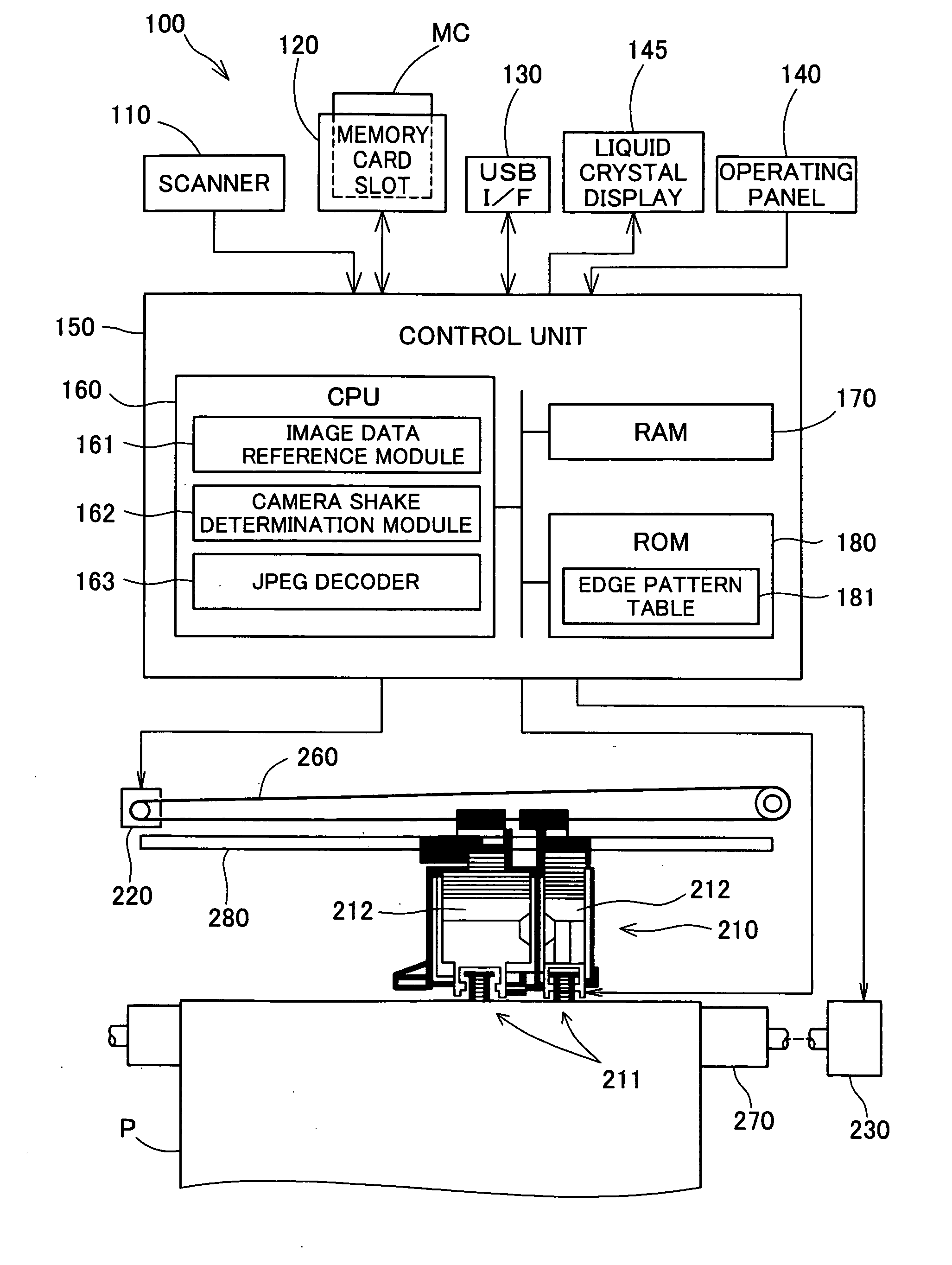
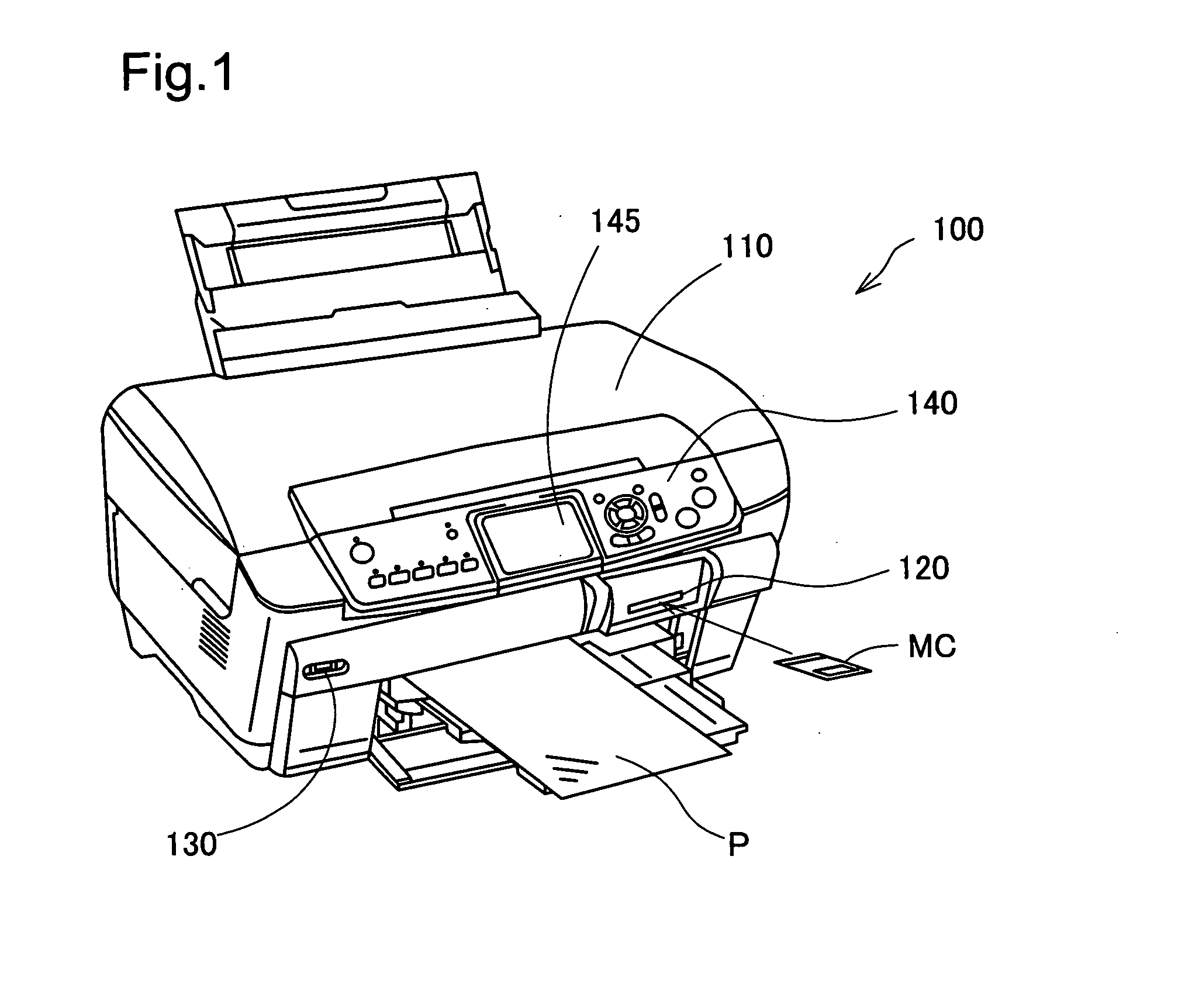
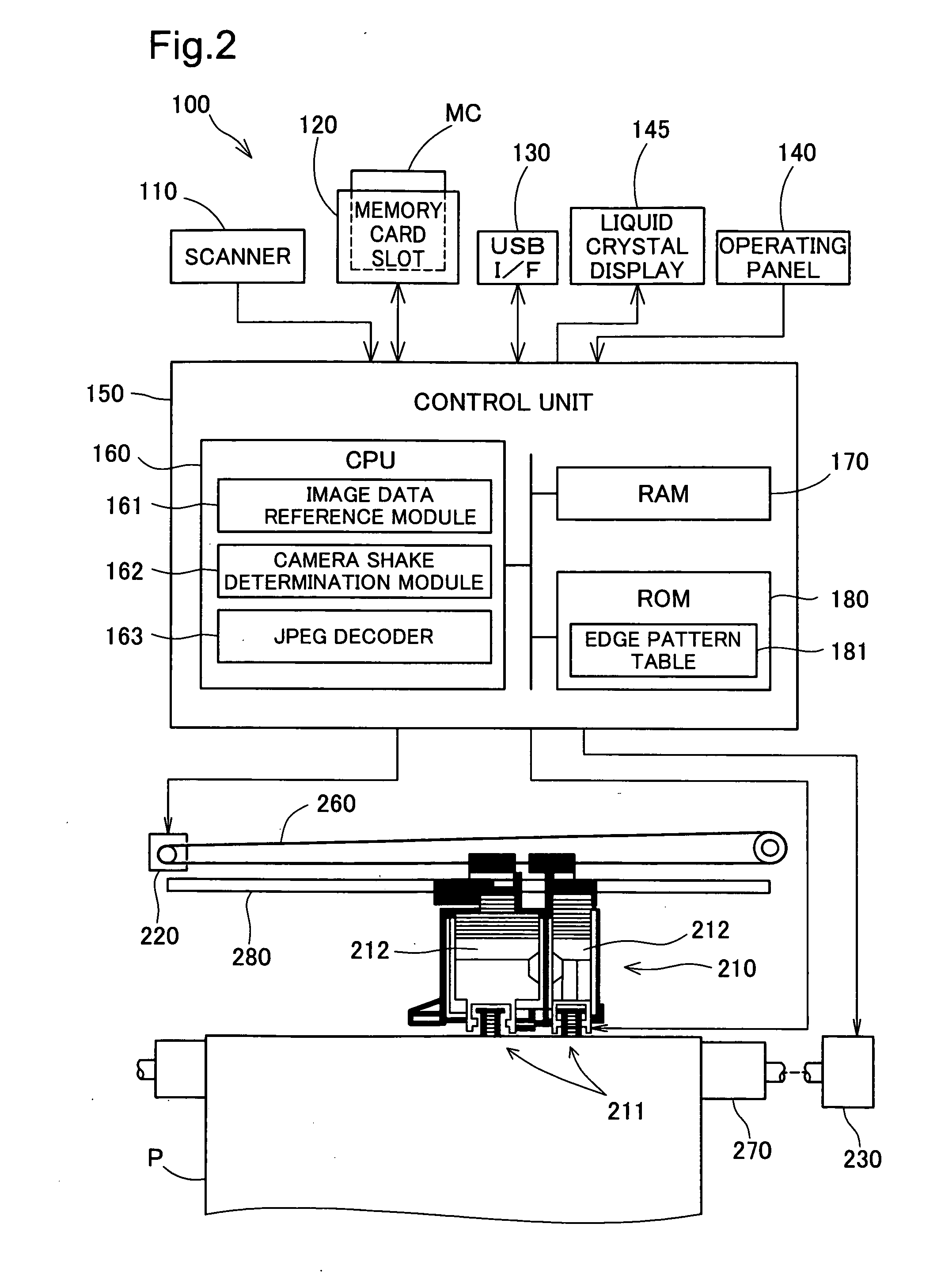
[0047]FIG. 1 illustrates the appearance of a printer 100 as an embodiment of the invention. The printer 100 is a multifunctional printer. The printer 100 is equipped with a scanner 110 that optically scans images, a memory card slot 120 for inserting a memory card MC on which image data has been recorded, and a USB interface 130 for connecting devices such as digital cameras. The printer 100 is able to print images scanned by the scanner 110, images read from the memory card MC, and images read from a digital camera via the USB interface 130 on printing paper P. The printer 100 can also print images input from a personal computer (not shown) connected by a printer cable or USB cable.

[0048]The printer 100 is equipped with an operating panel 140 for a variety of printing-related operations. A liquid crystal display 145 is provided in the center of the operating panel 140. Displayed on the liquid crystal display 145 are images read from the me...

3rd embodiment

3. 3rd Embodiment

[0120]FIG. 20 illustrates the appearance of a kiosk terminal as a third embodiment of the invention. The kiosk terminal 400 is a device located on streets or in various shops, and is equipped with a ticket-issuing function, ATM function, or various guided service functions.

[0121]The kiosk terminal 400 in this embodiment is equipped with a monitor 410, memory card reader 420, and printer 430. It is also internally equipped with a CPU, RAM, and ROM. The CPU executes a control program stored in ROM by loading the program in RAM, so as to carry out the above ticket-issuing function, ATM function, or various guided service functions. The CPU also runs the control program to carry out the same processes as the various processes described in the first embodiment (printing process and camera shake determination process). The kiosk terminal 400 can thus read image data from memory cards inserted into the memory card reader 420 and automatically select focused images to displ...


PUM


Abstract

The device employs a plurality of coefficients recorded in image data to detect whether edges are included per block, and determines as the blur level the proportion of edges, among the detected edges, in which the edge width is over a certain threshold. The device also determines, per block, coordinates composed of a first coefficient value representing frequency components in a first direction in the blocks and a second coefficient value representing frequency components in a second direction perpendicular to the first direction, and calculates the extent of bias in the distribution of the coordinates as the ellipticity. The device determines whether or not blurring has been produced by camera shake in an image based on the relationship between the blur level and ellipticity which have thus been determined.

Description

CLAIM OF PRIORITY[0001]The present application claims the priority based on Japanese Patent Applications No. 2006-342678 filed on Dec. 20, 2006 and No. 2007-264697 filed on Oct. 10, 2007, the disclosures of which are hereby incorporated by reference in their entirety.BACKGROUND[0002]1. Technical Field[0003]The invention relates to a technique for detecting blurring that has been produced in images as a result of camera shake.[0004]2. Related Art[0005]Digital still cameras have recently become popular, and the capacity of the memory cards used therein have been expanded. As a result, general users are storing greater amounts of images. Digital still cameras require no film and allow photographs to be taken more casually, often resulting in photographing with unintentional camera shake. As such, images are relatively often blurred due to camera shake, and attempts to print such images on a printing apparatus require normal images to be selected beforehand.[0006]It is extremely cumbers...

Claims


Application Information

Patent Timeline
IPC IPC(8): H04N1/409
CPCG06T7/0002H04N2201/0094H04N1/4092H04N1/0044
Inventor MIZOBE, KIMITAKE
Owner SEIKO EPSON CORP
Why Eureka
Try Eureka