Light source device, projector device, monitor device, and lighting device

a technology of monitor devices and light sources, applied in semiconductor lasers, instruments, optics, etc., can solve the problems of shortening affecting the service life of laser beam sources, and exceeding the tolerable temperature of laser beam sources

Active Publication Date: 2008-07-10
SEIKO EPSON CORP
View PDF1 Cites 60 Cited by
  • Summary
  • Abstract
  • Description
  • Claims
  • Application Information

AI Technical Summary

Benefits of technology

[0018]The lighting device of the fourth aspect of the present invention is able to structure a lighting device capab...

Problems solved by technology

However, there are concerns that the temperature of the laser beam source may exceed the tolerable temperature due to a failure in the cooling device, for example, or due to use of the image display device in an environment exceeding the tolerable temperature at which stable operation of the laser beam source is possible.
When the temperature of the laser beam source exceeds the tolerable temperature, then there is the problem that the output power of the laser beam source falls quickly when compar...

Method used


Image

  • Light source device, projector device, monitor device, and lighting device
  • Light source device, projector device, monitor device, and lighting device
  • Light source device, projector device, monitor device, and lighting device

Examples


first embodiment

A. First Embodiment

A1. Summary of System

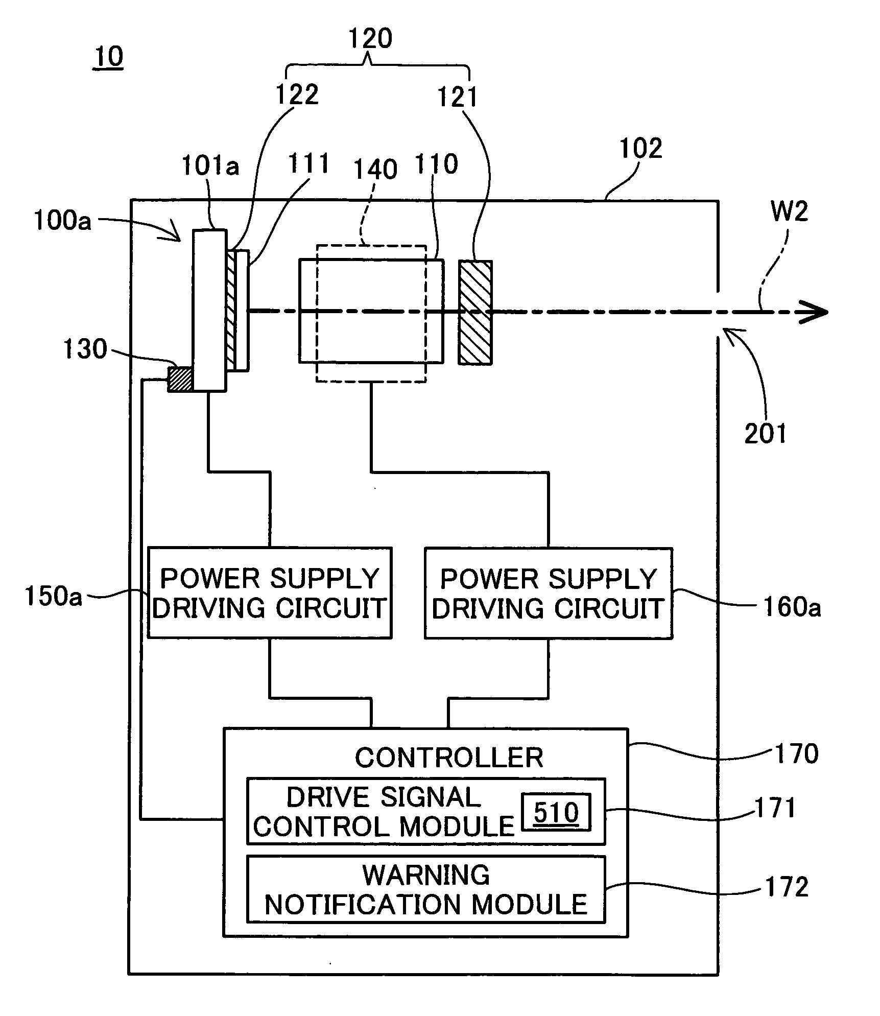
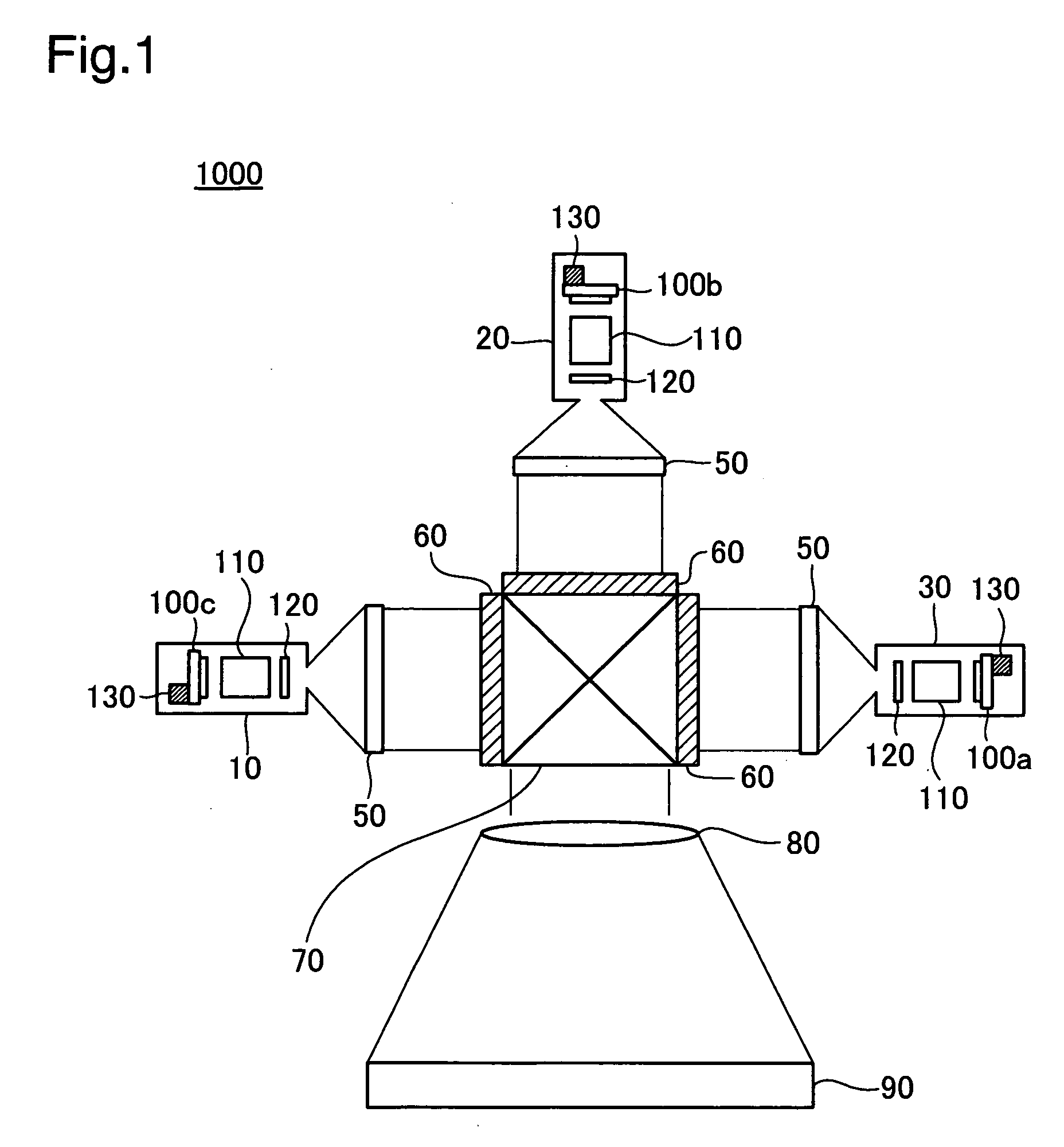
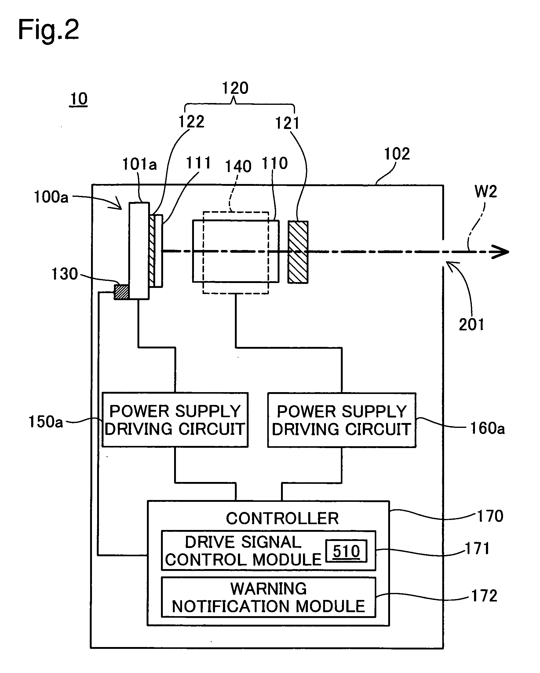
[0039]A projector will be described, in reference to FIG. 1 through FIG. 3, as an image display device in a first embodiment. FIG. 1 is an explanatory diagram illustrating the schematic structure of the projector in the first embodiment. FIG. 2 is a block diagram illustrating the structure of the light source device in the first embodiment.

[0040]As is shown in FIG. 1, a projector 1000 comprises light source devices 10, 20, and 30, homogenizing optical elements 50, light valves 60, a dichroic prism 70, and a projection lens 80.

[0041]The light source devices 10, 20, and 30 are used as light sources for the projector 1000. The light source device 10 outputs a red laser beam having a wavelength of approximately 650 nm; the light source device 20 outputs a green laser beam having a wavelength of approximately 540 nm; and the light source device 30 outputs a blue laser beam having a wavelength of approximately 430 nm. Note that because the laser bea...

second embodiment

B. Second Embodiment

[0081]In the second embodiment, a temperature sensor is disposed on a light source mount member to which the semiconductor laser device is attached.

[0082]B1. Detailed Structure of the Light Source Device

[0083]A light source device in a second embodiment will be described in reference to FIG. 8. As is shown in FIG. 8, the light source device of the second embodiment is provided with a light source mount member 180 and a sensor cover 131 in addition to each of the function blocks of the light source device of the first embodiment. Note that the structure of the light source in the second embodiment is provided with the same structures and functions as in the first embodiment, with the exception of the light source mount member and the temperature sensor attachment location, so explanations of redundant portions will be omitted.

[0084]The light source mount member 180 is made from a resin with thermostability and high thermal conductivity, and a black-colored coating...

third embodiment

C. Third Embodiment

[0090]In a third embodiment, not only is the temperature of the semiconductor laser device measured, but also the beam intensity of the visible beam that is outputted from the light source device is measured, and the output powers of the semiconductor laser devices 100a, 10b, and 100c of the three light source devices 10, 20, and 30 are controlled based on the temperatures and the beam intensities. The structure of the projector in the third embodiment is essentially identical to the structure of the projector in the first embodiment, explained with FIG. 1.

[0091]C1. Detailed Structure of the Light Source Device

[0092]The functional blocks of the light source device in the third embodiment will be explained in reference to FIG. 9. Note that for convenience in the figure, the power supply driving circuits for the light source devices 20 and 30, and structures aside from the temperature adjusting modules, are omitted.

[0093]As shown in FIG. 9, the light source device 1...


PUM


Abstract

The controller 170 controls the output power of the semiconductor laser device 100a depending on the temperature of the semiconductor laser device 100a acquired by the temperature sensor 130. The controller 170 references the correspondence table 510 when the sensor temperature Ts is obtained, obtains the output power PWs corresponding to the sensor temperature Ts, and controls the power supply driving circuit 150a so that the output power per unit time of the semiconductor laser device 100a will be the output power PWs. Thus increase in temperature of the semiconductor laser device is able to be prevented through reducing the output power by controlling the amount of power supplied to the semiconductor laser device. As a result, it is possible to prevent reductions in the service life of the semiconductor laser device, even when there is a failure in a cooling device that cools the semiconductor laser device, and even when the device is used in a high temperature environment not envisioned at the time of manufacturing.

Description

CROSS-REFERENCE TO RELATED APPLICATIONS[0001]The present application claims the priority based on Japanese Patent Application No. 2007-1571 filed on Jan. 9, 2007, Japanese Patent Application No. 2007-315577 filed on Dec. 6, 2007, the disclosure of which is hereby incorporated by reference in its entirety.BACKGROUND[0002]1. Technical Field[0003]The present invention relates to a light source device and to an image display device, a monitor device, and a lighting device comprising the light source device.[0004]2. Related Art[0005]Image display devices are in use wherein images are displayed by illuminating, with an illumination beam from a light source device, spatial optical modulator devices such as light valves and digital mirror devices (DMDs). The image display devices use a laser beam source that emits laser beams, for example, as a light source.[0006]The laser beam source produces heat through its operation, where the temperature of the device itself increases with the time of ...

Claims


Application Information

Patent Timeline
IPC IPC(8): H01S3/04
CPCG02F2001/3546G02F2203/60H01S3/109H04N9/3161H01S5/06804H01S5/14H04N9/3129H01S5/0617G02F1/3546
Inventor KAMIJIMA, SHUNJI
Owner SEIKO EPSON CORP
Why Eureka
Try Eureka