Ultrasonic Sanitation and Disinfecting Device and Associated Methods

Active Publication Date: 2008-09-18
ZIMEK TECH IP
View PDF30 Cites 18 Cited by
  • Summary
  • Abstract
  • Description
  • Claims
  • Application Information

AI Technical Summary

Benefits of technology

[0014]The device of the present invention is able to reach all areas in a space where air can penetrate, and, since the atomized particles have been found to remain airborne longer than conventional mists, treatment is more thor

Problems solved by technology

The sanitization and disinfection of enclosed spaces has become an issue of increasing importance owing to the possible presence of both natural and deliberately introduced contaminants.
Since most commercial buildings are “sealed,” that is, their windows cannot be opened, circulation of “fresh” air is typically not possible within a particular room.
The enclosed nature of modern spaces has led to such problems as “sick building syndrome,” since molds and mildews can flourish in enclosed, damp environments, and also to the possibility of the natural or deliberate introduction of more insidious threats to life, such as biological and chemical agents.
Some infectious agents, such as hepatitis virus and staph bacteria such as MRSA, are known to survive in areas such as hospitals and other healthcare facilities, and there, as well as in other places such as cruise ships, schools, locker rooms, and correctional facilities, pose a health threat.
In addition, other publicly used vehicles such as buses, boats, subway cars, trains, and taxis can be of concern.
These vehicles are seldom, if ever, cleaned to a level sufficient to ensure the eradication of infectious agents.

Method used


Image

  • Ultrasonic Sanitation and Disinfecting Device and Associated Methods
  • Ultrasonic Sanitation and Disinfecting Device and Associated Methods
  • Ultrasonic Sanitation and Disinfecting Device and Associated Methods

Examples


first embodiment

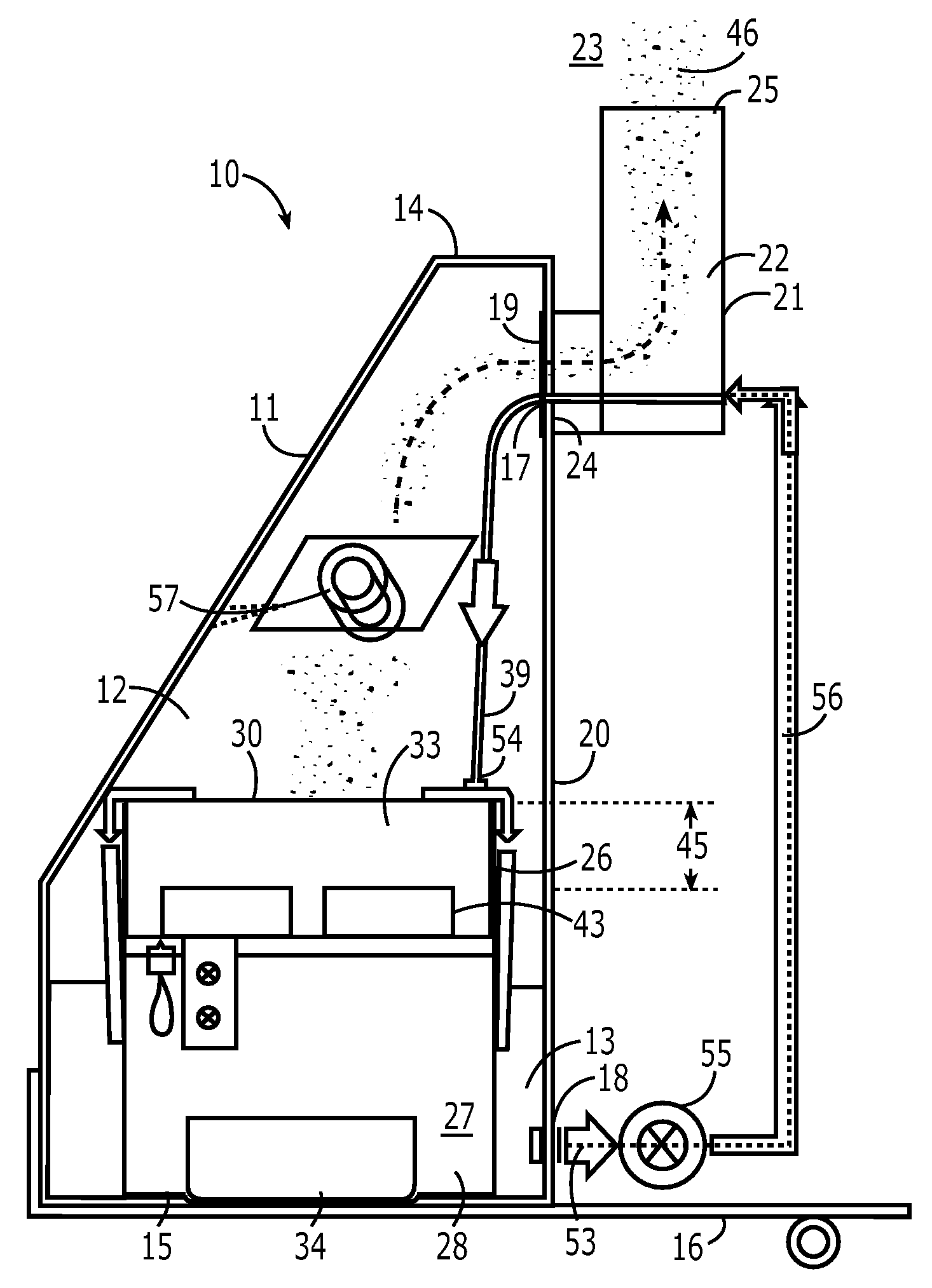
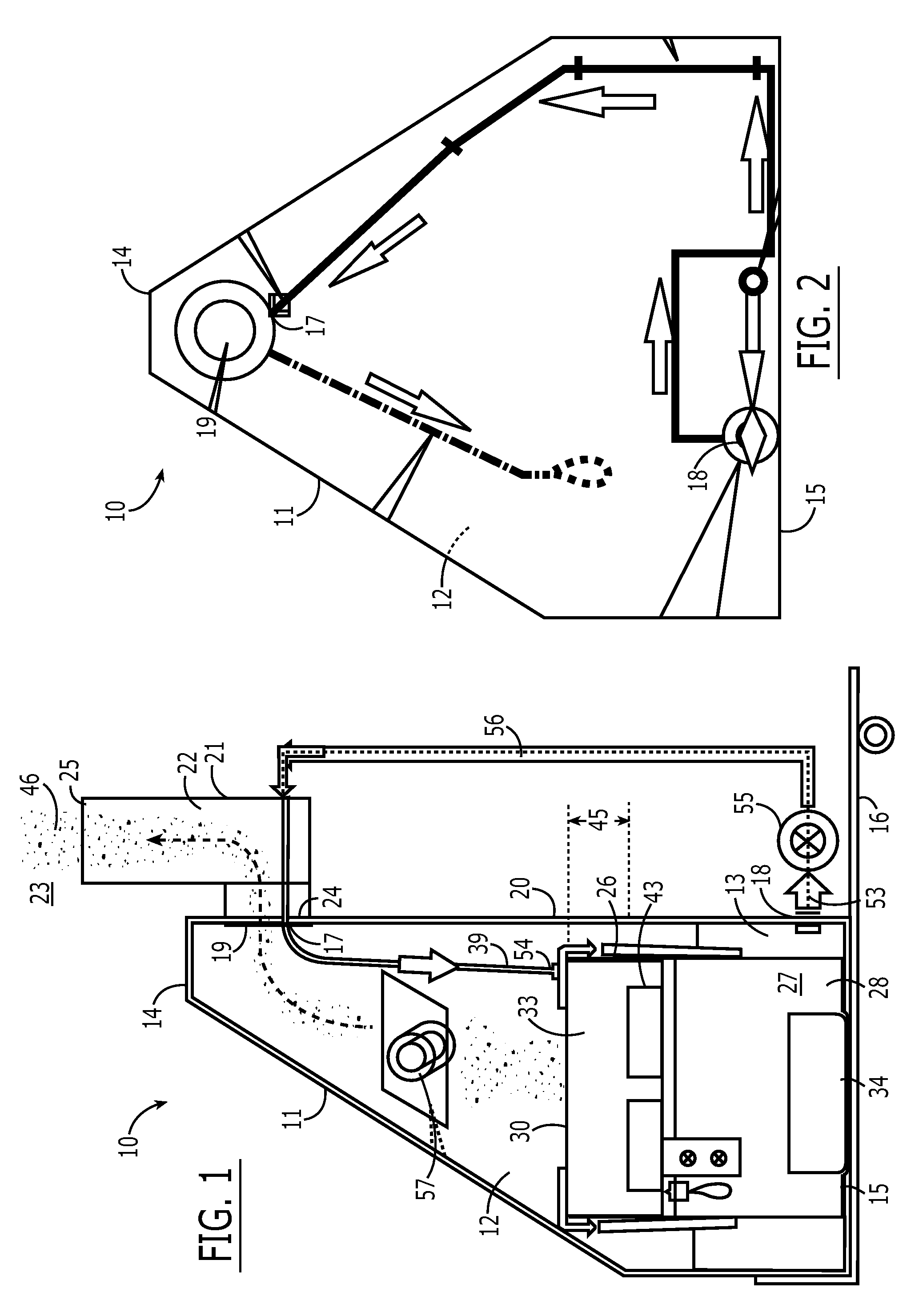
[0048]The device 10 in a first embodiment for sanitizing and disinfecting a space includes a tank 11 (FIGS. 1 and 2) that has an interior space 12 for holding an aqueous sanitizing liquid 13. In a particular embodiment, the tank's top end 14 is substantially smaller than its bottom 15. Further, the tank 11 may be configured for placement upon a wheeled cart 16 for ease of transport.

[0049]The tank 11 has a liquid line aperture 17 adjacent the top 14 and a liquid outlet 18 adjacent the bottom 15. The tank 11 can comprise a material adapted to maintain a static charge, such as, but not intended to be limiting, a high-density polyethylene (HDPE) material.

[0050]A micro-particle outlet 19 is positioned adjacent the tank's top 14 along the rear wall 20, and is in fluid communication with a chimney 21 having a bore 22 therethrough leading to a space 23 exterior of the tank 11. In a preferred embodiment, the chimney bore 22 has an elbow therein, shown by the dotted line in FIG. 1, meeting th...

embodiment 10

[0065]The shape of the device as illustrated herein is not intended to be limiting. For example, in an alternate embodiment 10′ shown in FIG. 12, the tank 11′ may have a chimney 21′ at the rear of the tank, which comprises a liquid inlet as well as an outlet for the dry mist created therein, and an air intake 60 toward the front of the tank 11′.

[0066]Yet another embodiment 70 (FIGS. 13-24) comprises a reactor vessel having a smooth upper edge 75 on the lip 76, and two inlets 77 for filling the vessel 74 (FIG. 13). A drain 78 permits emptying the vessel 74.

[0067]The vessel 74 in this embodiment 70 is adapted to hold four ultrasonic head arrays 43 as described above within four reactor holders 79 positioned in spaced relation within the vessel 74. Each reactor holder 79 comprises an “X”-shaped element having upwardly extending clips 80 at the end of each arm 81, the clips 80 positioned to surround the periphery of each ultrasonic head array.

[0068]In this embodiment 70 the reaction hol...

embodiment 150

[0076]In yet another embodiment 150, believed at the time of filing to represent a preferred embodiment, a reactor vessel 151 is provided that is substantially rectangular (FIGS. 27, 28, and 30). Supported by two walls 152 of the reactor vessel / cascade tray 151 are a plurality of, here, two, reactor cradles 153 each comprising a bottom support plate 154 affixed to a tensor pinching clip 156 via bolts through outer holes 325. The clip 156 comprises a substantially “U”-shaped element having a side 155 extending upward from an inwardly extending support shelf 323 having holes 324 meeting the bottom support plate's holes 325. The clip 156 further has a top 310 and outer portion 311 outwardly and downwardly extending from each of the sides 155, respectively. It will be understood that the use of such clip portions 156 is not intended as a limitation, and that alternative affixing means could be contemplated, such as hooks, etc.

[0077]The clip portions 156 are dimensioned to rest atop the ...


PUM


Abstract

A device for sanitizing and disinfecting a space includes a tank having an interior space for holding an aqueous sanitizing, disinfecting, and / or sterilizing liquid, a bottom sector, an air inlet sector, and an exhaust sector, inner walls of the exhaust sector and the air inlet sector forming a substantially “V”-shaped air pathway within the interior space. A liquid cascading reactor vessel is positioned within the bottom sector of the tank, a top edge of the reactor vessel in adjustably spaced relation from a notch in the “V”-shaped air pathway. A vibratable ultrasonic head array is positionable within and beneath a top edge of the reactor vessel and is submergable within the reactor vessel for vibrating the disc to form atomized micro-particles from the liquid. Air can be drawn into the air inlet, and the formed atomized micro-particles can be exhausted from the exhaust outlet.

Description

CROSS-REFERENCE TO RELATED APPLICATIONS[0001]This application is a continuation-in-part of application Ser. No. 11 / 624,317, filed Jan. 18, 2007, which is itself a continuation-in-part of application Ser. No. 11 / 277,176, filed Mar. 22, 2006.BACKGROUND OF THE INVENTION[0002]1. Field of the Invention[0003]The present invention relates to systems and methods for sanitizing and disinfecting enclosed spaces, and, more particularly, to such systems and methods that are capable of treating spaces three-dimensionally.[0004]2. Description of Related Art[0005]The sanitization and disinfection of enclosed spaces has become an issue of increasing importance owing to the possible presence of both natural and deliberately introduced contaminants. Since most commercial buildings are “sealed,” that is, their windows cannot be opened, circulation of “fresh” air is typically not possible within a particular room. Similarly, most houses are now effectively sealed, with mostly processed air being circul...

Claims


Application Information

Patent Timeline
IPC IPC(8): A61L2/025
CPCA61L9/14A61L2/22
Inventor SPARKS, DAVID W.
Owner ZIMEK TECH IP
Why Eureka
Try Eureka