

Method of detecting a ground fault and electrical switching apparatus employing the same
a ground fault and electrical switching technology, applied in the field of ground fault circuit breakers, can solve problems such as trip signals, and achieve the effect of reducing the cost and complexity of the electrical switching apparatus
Active Publication Date: 2008-11-13
EATON INTELLIGENT POWER LIMITED
View PDF3 Cites 15 Cited by
- Summary
- Abstract
- Description
- Claims
- Application Information
AI Technical Summary
Benefits of technology
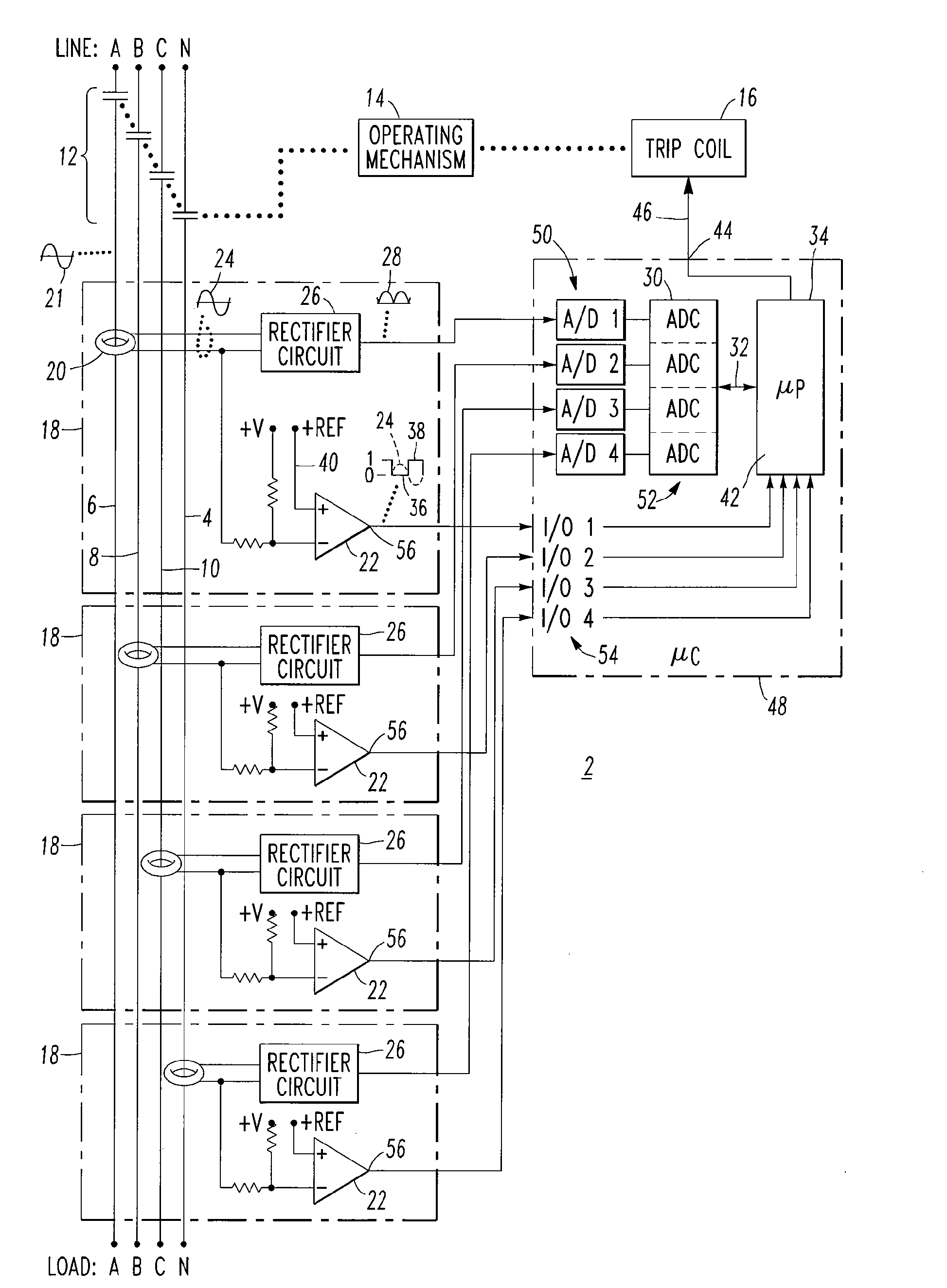
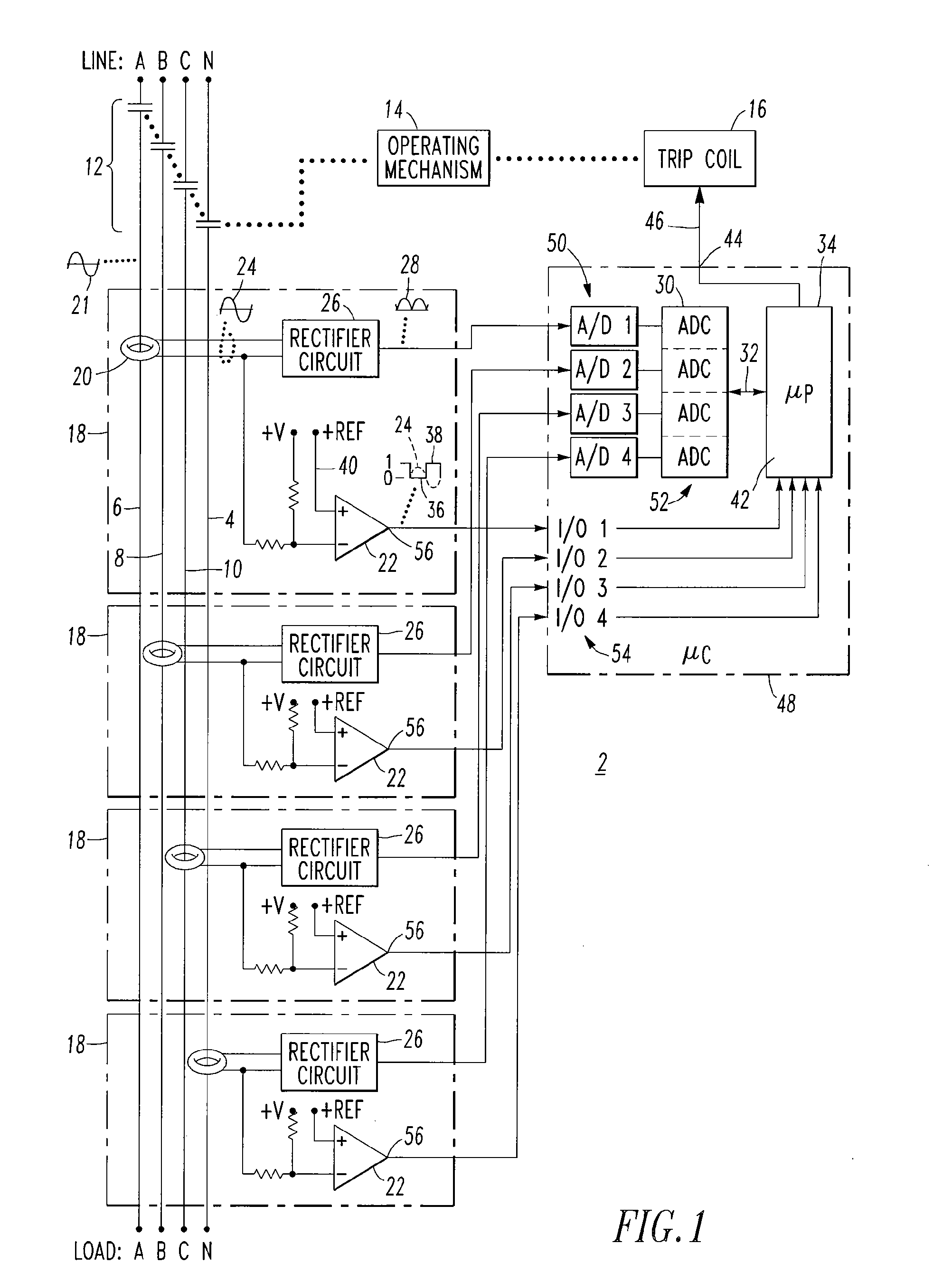
[0011]These needs and others are met by embodiments of the invention, which eliminate the need for any type of summing current transformer, thereby reducing the cost and complexity of the electrical switching apparatus, such as a circuit breaker.
Problems solved by technology
Method used
View moreImage
Smart ImageViewing Examples

Examples
example 1
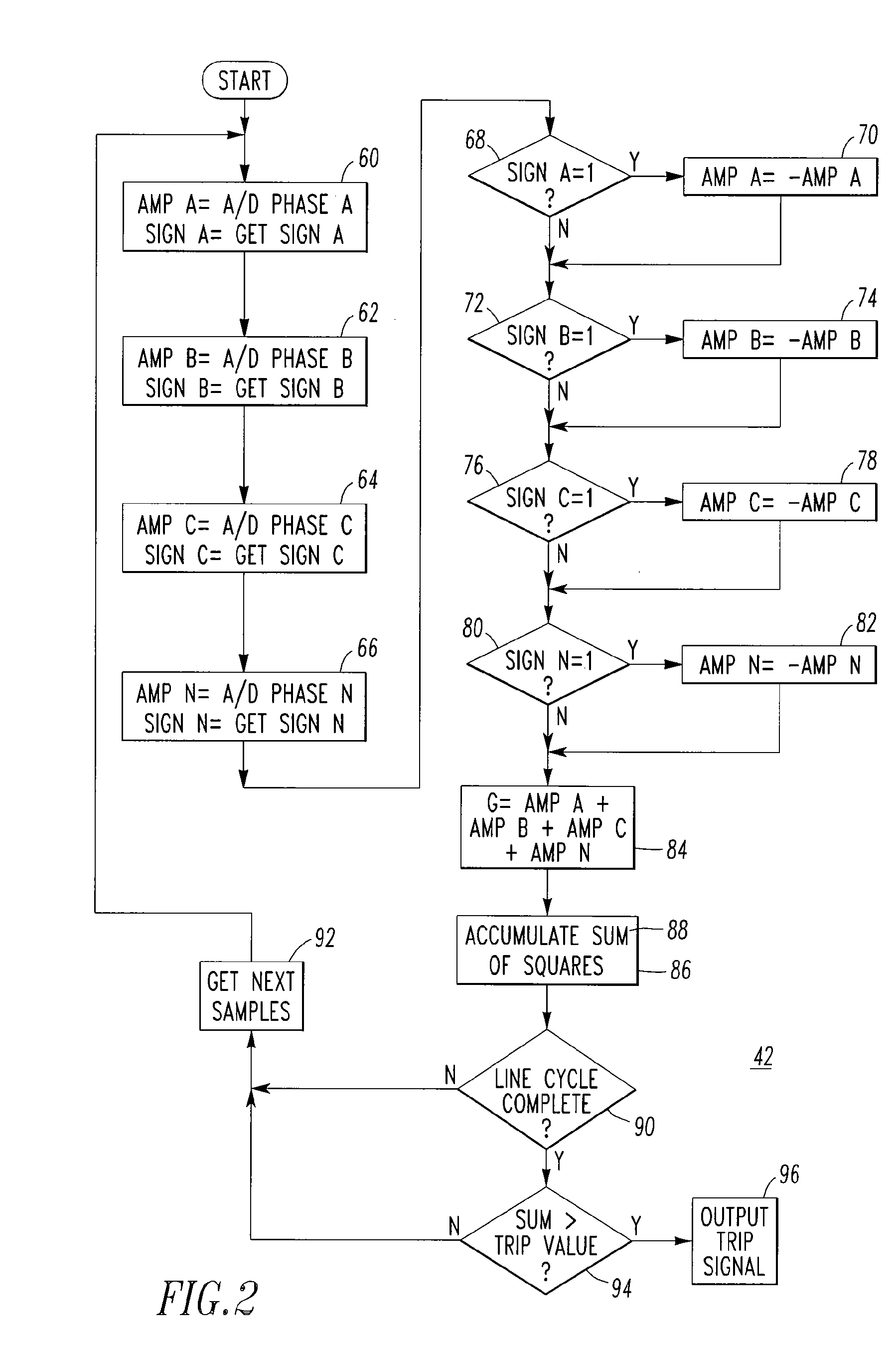
[0029]For a single power line plus neutral power line circuit breaker application, steps 62,64,72,74,76,78 are not performed, and the sum, at 84, is just for the signed digital values as read at 60,66, or as modified at 70,82.
example 2
[0030]As an alternative to Example 1, the number of phase power conductors may be two or more phase power conductors.
example 3
[0031]The circuit breaker 2 of FIG. 1 includes a frame rating, and the predetermined value of step 94 is a predetermined percentage of the frame rating.
Login to View More PUM
 Abstract
A circuit breaker includes for each neutral and phase power conductor, a current sensor sensing an alternating current flowing in a corresponding power conductor, a comparator determining whether the sensed alternating current is positive or negative, a rectifier rectifying the sensed alternating current to provide a rectified current value, and an analog-to-digital converter converting the rectified current value to a signed digital value having a positive sign. A processor cooperates with the comparators and the analog-to-digital converters and includes a routine that changes the positive sign of the signed digital value to a negative sign if the sensed alternating current is negative, adds the signed digital value for each power conductor to provide a sum, and employs the sum to determine whether to output a ground fault signal. The processor further cooperates with an operating mechanism to trip open separable contacts responsive to the ground fault signal.
Description
BACKGROUND OF THE INVENTION[0001]1. Field of the Invention[0002]This invention pertains generally to electrical switching apparatus and, more particularly, to ground fault circuit breakers. The invention also relates to methods of detecting a ground fault.[0003]2. Background Information[0004]Circuit breakers are used to protect electrical circuitry from damage due to an overcurrent condition, such as an overload condition or a relatively high level short circuit or fault condition. For example, in response to the overcurrent condition, a spring powered operating mechanism is unlatched, in order to open the separable contacts of the circuit breaker and, thus, interrupt current flow in a protected power system. Examples of circuit breakers are disclosed in U.S. Pat. Nos. 5,910,760; 6,137,386; 6,144,271; and 6,853,279, which are incorporated by reference herein.[0005]In many applications, the circuit breaker also provides ground fault protection. Typically, an electronic circuit detect...
Claims
Login to View More Application Information
Patent Timeline
 IPC IPC(8): H01H83/00G01R31/14H02H3/16
CPCG01R31/025H01H83/226H02H3/165G01R31/52
InventorSHAAK, TODD M.CARLINO, HARRY J.
OwnerEATON INTELLIGENT POWER LIMITED