Battery pack

Active Publication Date: 2008-11-20
SONY CORP
View PDF10 Cites 15 Cited by
  • Summary
  • Abstract
  • Description
  • Claims
  • Application Information

AI Technical Summary

Benefits of technology

[0011]According to the one embodiment of the present invention, the battery cells in the state of being partitioned by the support plates have terminals on one side being fixed in parallel to the partition plate by the tab(s), and have terminals on the other side in at least one layer being fixed in parallel to the partition plate by the tab(s), and the battery cells having terminals on the other side being fixed by the tab are supported by projected pieces formed on the support plates for clamping the battery cells. This ensures that the battery cells can be prevented from being loosened and released from the partition member when handled by hand, and an improved assembleability can be attained.
[0012]In addition, according to another embodiment of the invention, in the condition where the battery cells arranged in two rows and four layers, the battery cells in each set of paired battery cells being connected in parallel, and the four sets of parallel-connected paired battery cells being connected in series, are partitioned by the support plates, the terminals on one side are fixed substantially in parallel to the partition plate by the tabs. As for the terminals on the other side, the main circuit board and the lowest battery cell in each row and the second lowest battery cell in each row are electrically c

Problems solved by technology

Therefore, depending on the manner in which the electrode tabs are wired, handling of the battery cells by the manufacturer o

Method used


Image

  • Battery pack
  • Battery pack
  • Battery pack

Examples


Example

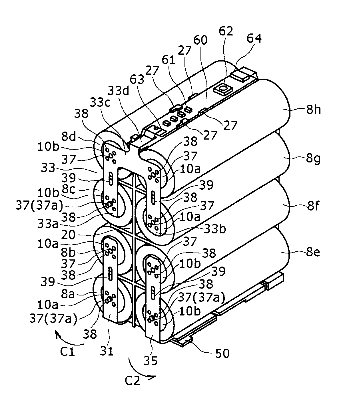
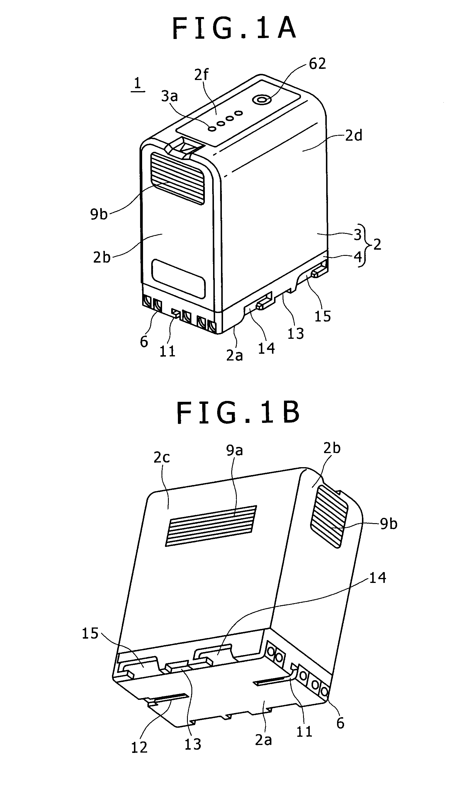
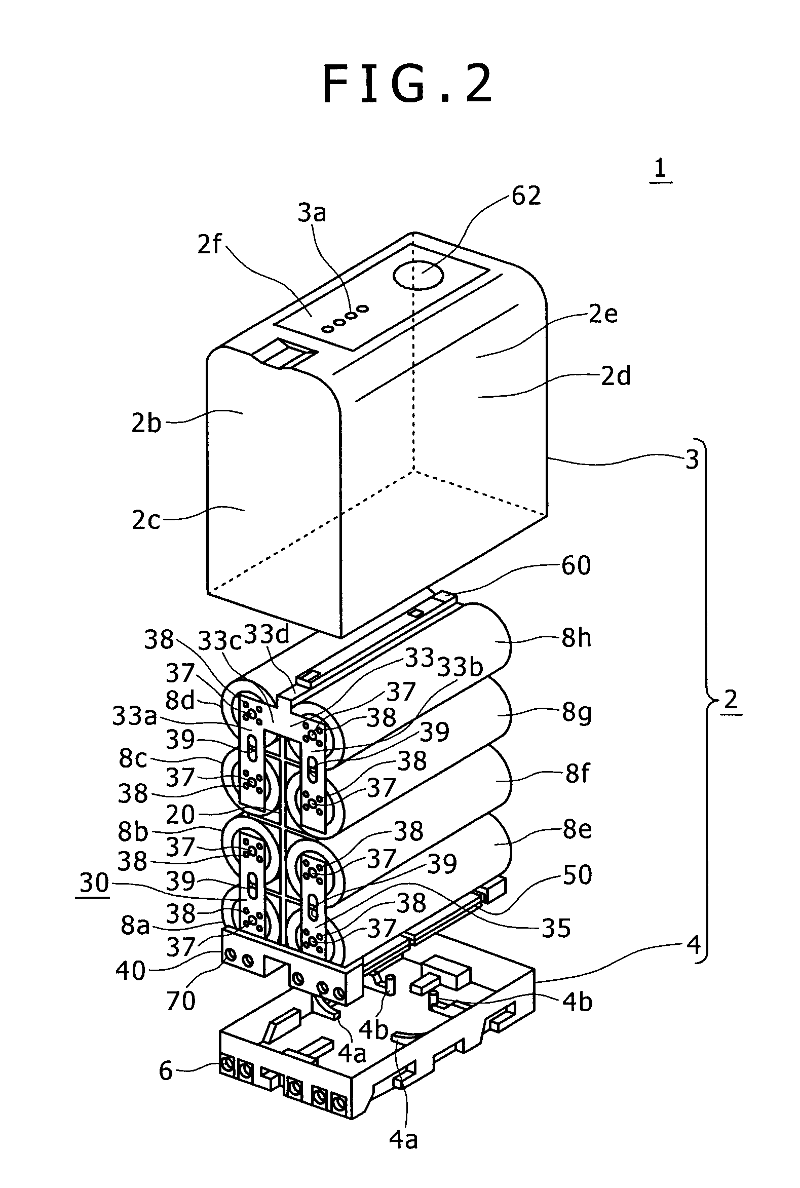
[0050]Now, a battery pack based on the present invention will be described in detail below, referring to the drawings. The battery pack based on the present invention is prepared in two kinds, according to the number of battery cells 8 contained in a casing 2, for example, an L-size battery pack 1 shown in FIGS. 1A, 1B and 2 and an S-size battery pack 100 shown in FIGS. 3A, 3B and 33. Specifically, the L-size battery pack 1 contains eight battery cells 8a to 8h (hereinafter, the battery cells 8a to 8h will also be referred to simply as the battery cells 8) in two rows and four layers as shown in FIG. 2, while the S-size battery pack 100 contains four battery cells 8i to 8l (hereinafter, the battery cells 8i to 8l will also be referred to simply as the battery cells 8) in two rows and two layers as shown in FIG. 33. The battery packs 1, 100 based on the present invention each have a roughly rectangular casing 2 in which the battery cells 8 are contained and which has a terminal part ...


PUM


Abstract

Disclosed herein is a battery pack including: a plurality of cylindrical battery cells arranged in at least two rows and a plurality of layers; and a partition member for partitioning the battery cells; wherein the partition member includes a partition plate and support plates; the battery cells in the state of being partitioned by the support plates have terminals on one side being fixed substantially in parallel to the partition plate by an electrode tab or tabs, and have terminals on the other side in at least one layer being fixed substantially in parallel to the partition plate by an electrode tab or tabs; and the support plates for clamping the battery cell of which the terminal on the other side is fixed by the electrode tab are formed respectively with projected pieces.

Description

CROSS REFERENCES TO RELATED APPLICATIONS[0001]The present invention contains subject matter related to Japanese Patent Application JP 2007-130883 filed in the Japan Patent Office on May 16, 2007, the entire contents of which being incorporated herein by reference.BACKGROUND OF THE INVENTION[0002]1. Field of the Invention[0003]The present invention relates to a battery pack in which battery cells are prevented from being loosened to come out of position.[0004]2. Description of the Related Art[0005]A battery pack includes a plurality of cylindrical battery cells arranged in a plurality of rows and a plurality of layers, a partition member for partitioning the battery cells, electrode tabs for electrically connecting terminals of the battery cells partitioned by the partition member, a lower case for containing the battery cells electrically connected trough the electrode tabs, and an upper cover for covering the lower case containing the battery case therein, and is detachably attache...

Claims


Application Information

Patent Timeline
IPC IPC(8): H01M2/10H01M50/529
CPCH01M2/24H01M2/105Y02E60/10H01M50/213H01M50/529
Inventor NAITO, MASAKAZUBANNAI, YOSHIYUKISUZUKI, HIDEYUKI
Owner SONY CORP
Why Eureka
Try Eureka