Eureka AIR delivers breakthrough ideas for toughest innovation challenges, trusted by R&D personnel around the world.

Mechanism coupling structure of molded case circuit breaker

Active Publication Date: 2018-01-25
LSIS CO LTD
View PDF4 Cites 0 Cited by
  • Summary
  • Abstract
  • Description
  • Claims
  • Application Information

AI Technical Summary

Benefits of technology

The present invention introduces a mechanism coupling structure for a molded-case circuit breaker to prevent the lower link from being released during a fault. This is achieved by using a discharge groove on the lower link to reduce the pressure generated during interruption. Additionally, the rotating pin has a protruding portion to prevent it from being released from the lower link even when utilizing the force caused by arc pressure. These features provide better reliability and durability to the circuit breaker.

Problems solved by technology

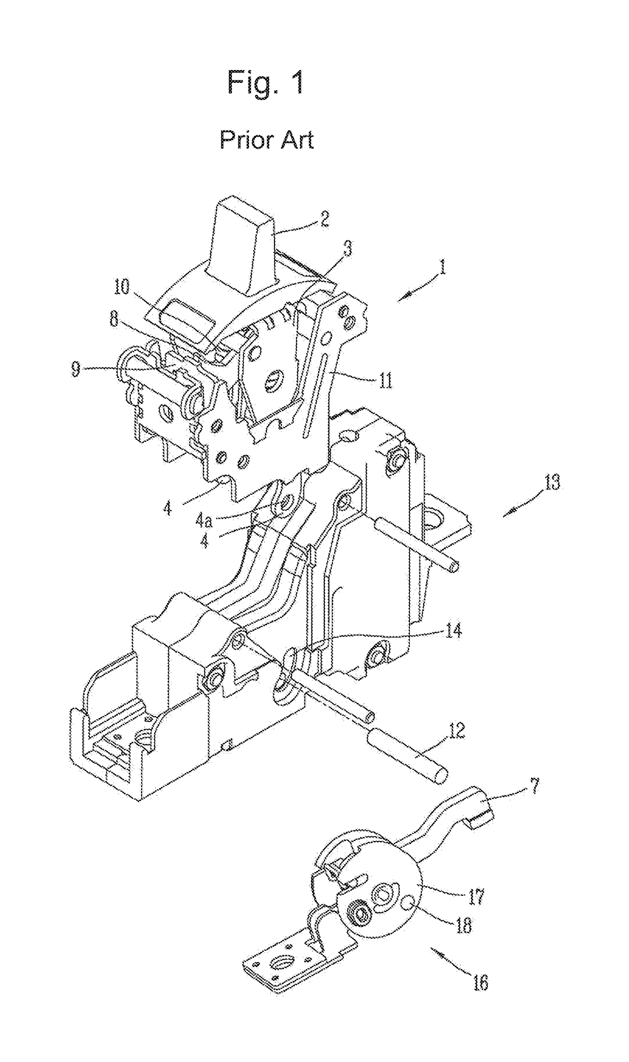
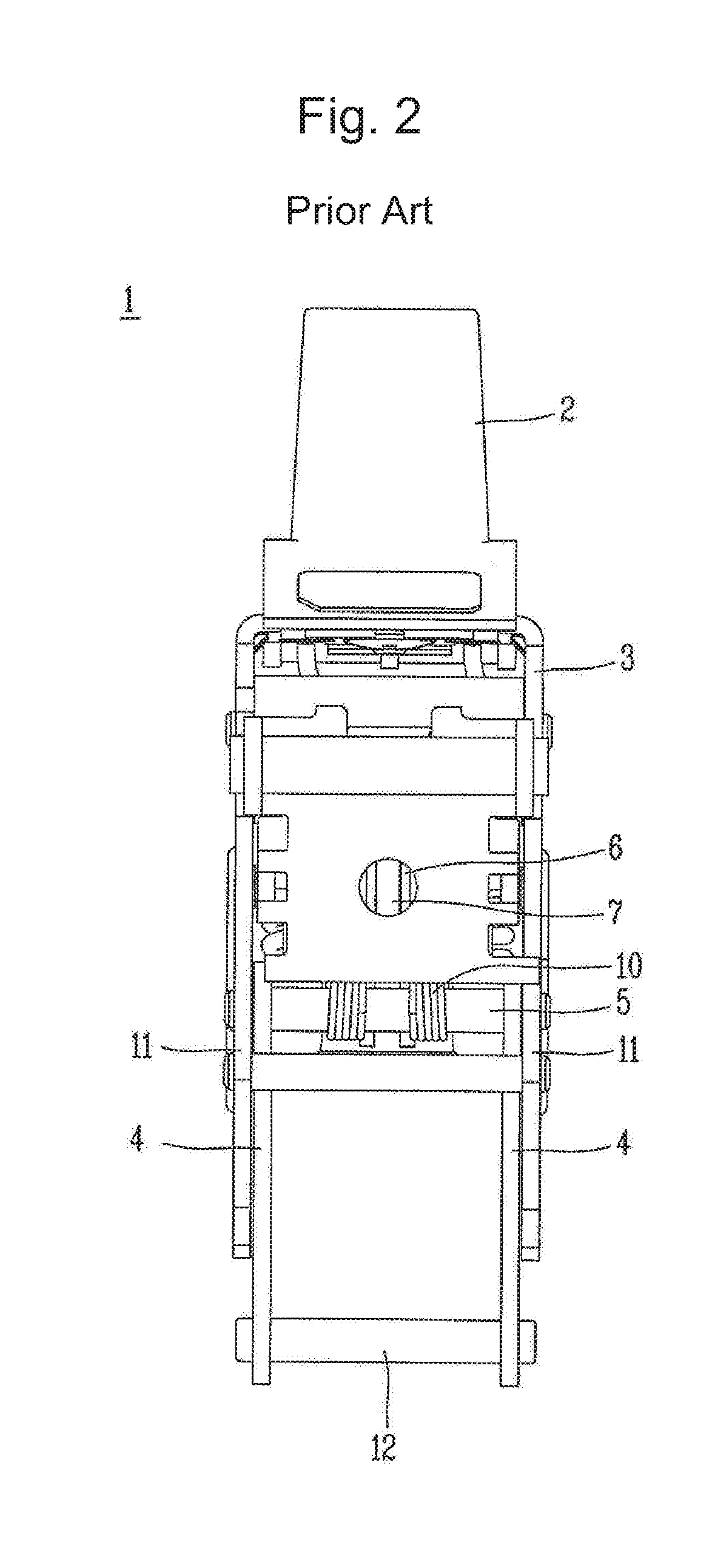
However, in the coupled state of such a mechanism, an internal pressure generated at the time of interruption may leak along a fine gap between the components to act on the lower link 4.

Method used


Image

  • Mechanism coupling structure of molded case circuit breaker
  • Mechanism coupling structure of molded case circuit breaker
  • Mechanism coupling structure of molded case circuit breaker

Examples


Embodiment Construction

[0034]Hereinafter, a preferred embodiment of the present invention will be described in detail with reference to the accompanying drawings to such an extent that the present invention can be easily implemented by a person having ordinary skill in the art to which the present invention pertains, but it does not mean that the technical concept and scope of the present invention are limited due to this.

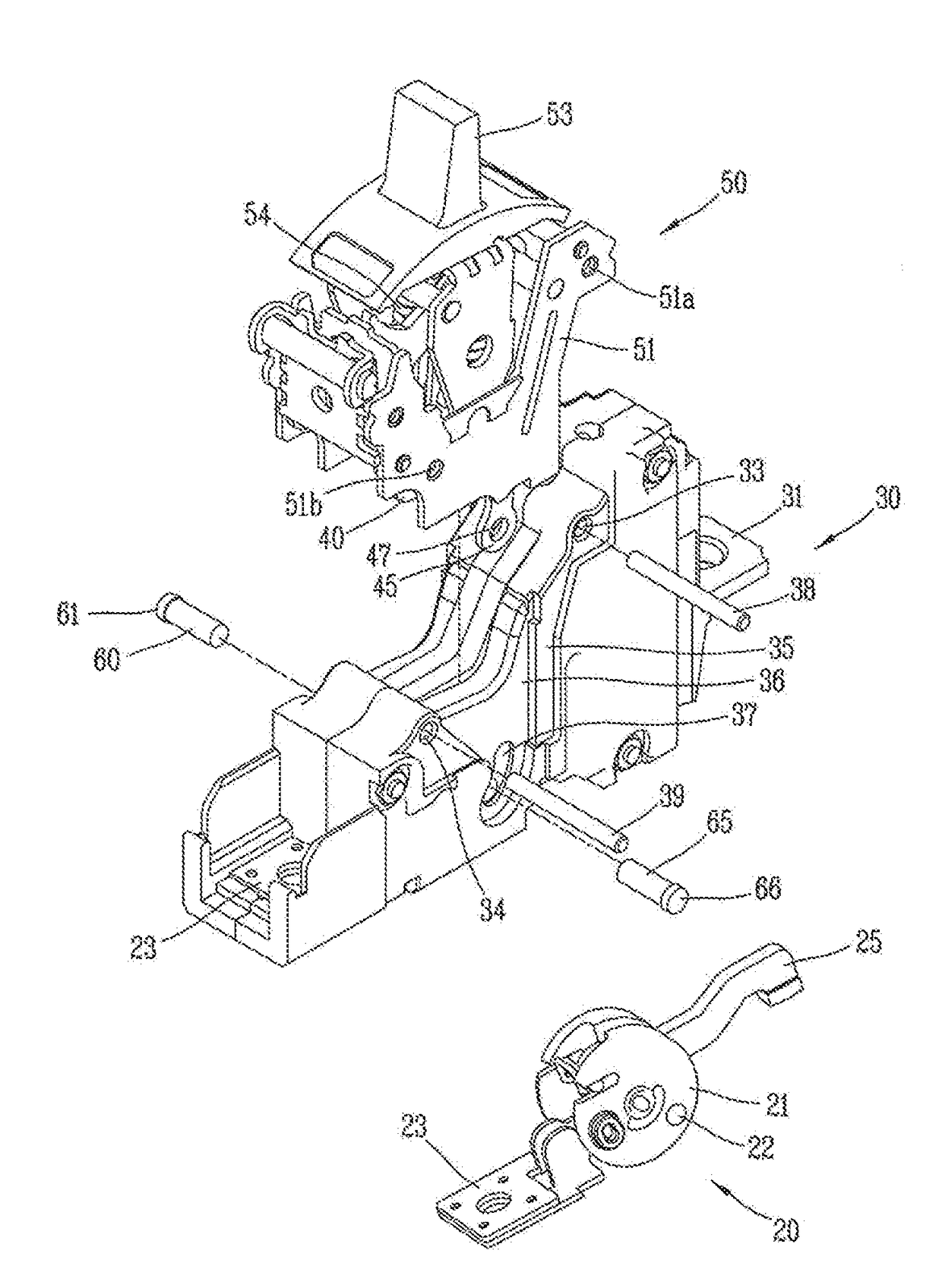
[0035]FIG. 5 is a perspective view illustrating a mechanism coupling structure of a molded-case circuit breaker according to an embodiment of the present disclosure, and FIG. 6 is a front view illustrating a switch mechanism of a molded-case circuit breaker according to an embodiment of the present disclosure, and FIG. 7 is a side view in which a mechanism of a molded-case circuit breaker according to an embodiment of the present disclosure is in a coupled state, and FIGS. 8 and 9 are perspective views illustrating a rotating pin and a lower link applied to a mechanism of a molded-case c...


PUM


Abstract

A mechanism coupling structure of a molded-case circuit breaker according to an embodiment of the present disclosure including a shaft to one side of which a movable contactor is coupled, and on a part of which a rotating pinhole is formed in a penetrating manner; a base assembly into which the shaft is rotatably accommodated and coupled, a switch mechanism coupled to an upper portion of the base assembly and exposed with a first lower link and a second lower link at a lower side thereof, and a rotating pin coupled in a penetrating manner to the first lower link, second lower link and rotating pinhole may be provided therein, wherein the rotating pin has a protruding portion for release prevention at one end thereof.

Description

CROSS-REFERENCE TO RELATED APPLICATIONS[0001]Pursuant to 35 U.S.C. §119(a), this application claims the benefit of earlier filing date and right of priority to Korean Patent Application No. 10-2016-0093670, filed on Jul. 22, 2016, the contents of which are all hereby incorporated by reference herein in its entirety.BACKGROUND OF THE INVENTION1. Field of the Invention[0002]The present disclosure relates to a mechanism coupling structure of a molded-case circuit breaker, and more particularly, to a mechanism coupling structure of a molded-case circuit breaker for preventing a lower link from being released from a rotating pin by an arc pressure generated at the time of breaking.2. Description of the Related Art[0003]In general, Molded-Case Circuit Breaker (MCCB) is an electric device for automatically breaking a circuit in the event of an electrical overload or short circuit to protect the circuit and a load thereof. The molded-case circuit breaker may largely include a terminal porti...

Claims


Application Information

Patent Timeline
IPC IPC(8): H01H71/02H01H71/10
CPCH01H71/10H01H71/0207H01H71/1009H01H71/528H01H73/18H01H71/0214
Inventor YOO, SUNGROKOH, KIHWAN
Owner LSIS CO LTD
Why Eureka
Eureka Blog
Learn More