Eureka AIR delivers breakthrough ideas for toughest innovation challenges, trusted by R&D personnel around the world.

Torque socket

Pending Publication Date: 2021-10-21
CHUANG WEI CHIEH
View PDF4 Cites 0 Cited by
  • Summary
  • Abstract
  • Description
  • Claims
  • Application Information

AI Technical Summary

Benefits of technology

The present invention is a torque socket that can adjust the torque of a drive head and prevent it from being released. The torque socket includes a shaft rod with a core shaft and a sleeve slot for inserting a drive head. The core shaft has a shaft hole and at least one cut groove with a first friction surface while the shaft slot has a second friction surface. The shaft cylinder has a recess with a ball hole and an elastic tubular member with a receiving hole for a ball member that constantly protrudes. The mobile ratchet can axially move elastically on the core shaft and the fixed ratchet prevents rotation in the accommodation slot.

Problems solved by technology

Because the drive head of the screwdriver is formed with a fixed shape and dimension, thus another drive head having a different shape and dimension cannot be utilized for replacement.
The screwdriver having the transmission structure composed of the spring and the steel ball can control the outputted quantified torque, but only a point contacting status is established when the steel ball being released from the spring, thus the components are fragile and very easy to be deformed and damaged, and the limited outputted torque value is relatively unstable.
In addition, because the above-mentioned screwdriver is provided with the transmission structure composed of the spring and the steel ball, the dimension of the screwdriver is unable to be effectively reduced, thus the screwdriver is not suitable to be applied in the locking operation of a precision instrument.
Moreover, a sleeve slot of a conventional torque socket is used for allowing a drive head to be disposed, but the drive head and the sleeve slot cannot be tightly connected due to the manufacturing tolerance or wearing, thus the drive head may be released from the sleeve slot, and a poor operating performance may be caused during the actual operation.
As such, the skilled people in the art has developed a means of disposing a magnet at an inner end of the sleeve slot for magnetically attracting the drive head so as to prevent the drive head from being released from the sleeve slot; however, a drive head made of a non-magnetic-conducting material, for example iron, is unable to be provided with the magnetic attracting effect by utilizing the magnet, so that a situation of releasing is still needed to be concerned.

Method used


Image

  • Torque socket
  • Torque socket
  • Torque socket

Examples


Embodiment Construction

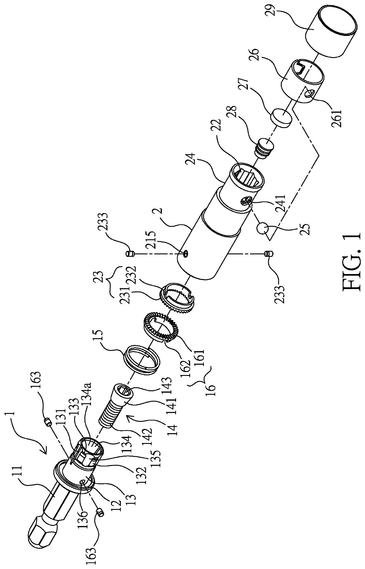
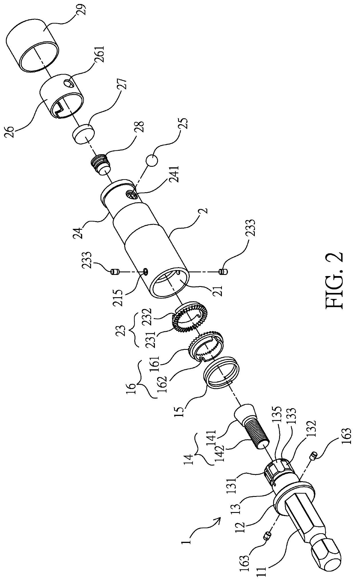
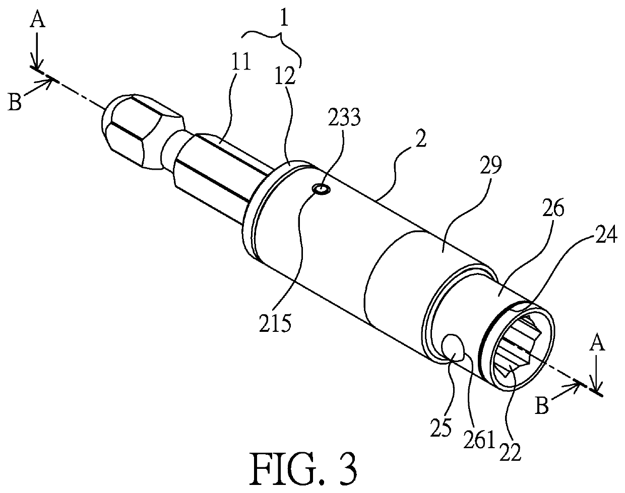
[0028]Please refer from FIG. 1 to FIG. 5, a torque socket having a shaft rod 1 and a shaft cylinder 2 is disclosed.

[0029]The shaft rod 1 is formed as a rod member, one axial side thereof has an insertion tenon 11 having a cross section formed in a non-circular shape, for example a hexagonal shape, a flange 12 is radially formed at an inner side of the insertion tenon 11, so that two sides of the flange 12 can be arranged to be adjacent to the shaft cylinder 2 and connecting rod (known as prior art and not shown in figures) at a bottom end of a handgrip of a rotation tool, for example a screwdriver. Another side of the flange 12 is extended with a core shaft 13 having a circular cross section, an outer circumferential surface of the core shaft 13 is axially formed with at least one cut groove 131, thereby providing a proper elasticity to the core shaft 13. In addition, the outer circumferential surface of the core shaft 13 is formed with a concave first friction surface 132 and a con...


PUM


Abstract

A torque socket includes: a shaft rod, having two sides thereof axially extended with an insertion tenon and a core shaft, wherein the core shaft is axially formed with a shaft hole; and a shaft cylinder, having two sides thereof respectively formed with a shaft slot and a sleeve slot allowing a drive head to be inserted, wherein the shaft cylinder has a recess which is radially formed with a ball hole allowing a ball member to be disposed, the recess has an elastic tube member radially formed with a receiving hole allowing the ball member to be received, so that an elastic effect of the elastic tube member can be provided to the ball member for allowing the ball member to constantly protrude from the sleeve slot, and the ball member is able to be elastically latched in a latch slot of the drive head.

Description

BACKGROUND OF THE INVENTIONField of the Invention[0001]The present invention relates to a torque socket, especially to a torque socket having functions of allowing a drive head to be rapidly connected and preventing the drive head from being released, wherein one end of the torque socket is sleeved with a manual, a pneumatic or an electric rotation tool and another end thereof is sleeved with the drive head.Description of the Related Art[0002]A screwdriver is mainly composed of a handgrip and a drive rod having a drive head, the drive head is generally categorized into a flat type or a cross type for matching with a flat or a cross recess formed at the top end of a screw, thereby enabling the screw to be locked or released. Because the drive head of the screwdriver is formed with a fixed shape and dimension, thus another drive head having a different shape and dimension cannot be utilized for replacement.[0003]In view of the disadvantage of the above-mentioned screwdriver, the skill...

Claims


Application Information

Patent Timeline
IPC IPC(8): B25B23/142B25B23/00B25B23/12
CPCB25B23/1427B25B23/12B25B23/0035F16D7/10B25B13/06
Inventor CHUANG, WEI-CHIEH
Owner CHUANG WEI CHIEH
Why Eureka
Eureka Blog
Learn More