Optical and electrical hybrid connector

Inactive Publication Date: 2006-05-11
J FITNESS LLC
View PDF13 Cites 20 Cited by
  • Summary
  • Abstract
  • Description
  • Claims
  • Application Information

AI Technical Summary

Benefits of technology

[0017] The present invention relies upon the knowledge of design considerations needed to achieve a hybrid plug and socket connector with a Z-tolerant central floating optical fiber coupler and a Z-tolerant axial peripheral electrical contact array, allowing for rapid, inexpensive, axial-position-tolerant, self-wiping, reliable connections

Problems solved by technology

Second, inherent features required for good electrical connections (e.g., good physical contact with contact element wiping, low axial positional mating accuracy, and no need of contact finishing after assembly) are different, and often contrary, to those features required for good optical fiber coupling (avoiding physical contact which damages fiber faces, high axial positional mating accuracy, and required post-assembly fiber-end finishing steps).
Direct physical contact between optical fibers damages the cladding that keeps light within the fibers, scratches the optical fiber face where light is transmitted, or shatters the fiber body entirely, all of which reduce fiber light transmission or renders the fiber useless.
Therefore, there is little Z-axis positional accuracy typically required to make an electrical connection work well.
In contrast, optical connectors are not so tolerant of error.
First, axial (Z-axis) movement of optical fibers away from each other results in a loss of optical coupling; while axial movement toward each other must be carefully limited in order to prevent collisions between the fiber ends.
Such collisions can seriously damage most optical fiber faces.
Second, a seemingly minor lateral positional misalignment of a pair of optical fibers typically leads to huge fiber coupling losses.
These precision components—including laser drilled ferrules and milled stainless-steel couplers—translate to a high connector cost.
All told, when taking into consideration the above inherent limitations, electrical and optical connectors have physical contact, positional accuracy, and post-assembly requirements that come directly into conflict, and such conflicting requirements are not readily simultaneously satisfied.
These Lemo connectors, by failing to simultaneously optimize the different requirements of optical and el

Method used


Image

  • Optical and electrical hybrid connector
  • Optical and electrical hybrid connector
  • Optical and electrical hybrid connector

Examples


Example

Example 1

[0082] A working version of the optical and electrical hybrid connector was constructed in accordance with the disclosed invention. Light throughput was recorded in using an EXFO optical power meter (Exfo, Quebec, Canada) through 100 micron glass / glass optical fiber (FV100 / 101 / 125 silica clad fiber, Polymicro Technologies, Phoenix Ariz.) as the shaft plug is inserted in the receptacle socket. Axial displacement relative to the final, fully inserted position was recorded at intervals of 1 mm over the final 1 cm of insertion. Referring now to FIG. 13A, the recorded optical power values were plotted as line 312, which is a function of relative optical throughput vs. distance from the fully inserted connector position. There is noted plateau region 317 spanning the final 2 mm of insertion, in which the intensity of transmitted light does not fall by more than 12%, demonstrating (by definition) an axial-position tolerance, as intended in the present invention.

[0083] The above ...

Example

Example 2

[0085] An optical and electrical hybrid connector was constructed wherein optical coupler 225 was an SMA optical coupler / connector with integrated reversed beam expander optics (Model F230SMA-A collimator, Thorlabs, Newton, N.J.), and further, spring 229 was omitted such that the physical floating action of coupler 225 was completely eliminated. The design, however, remains Z-tolerant, as the collimating lens now provides a lens-coupled axial-position-tolerance.

[0086] As before, light throughput was recorded using an optical power meter through 100 micron glass / glass optical fiber as the probe was inserted into the connector. Axial displacement from the final, fully inserted position was recorded at intervals of 1 mm over the final 1 cm of insertion. Referring now to FIG. 13B, the recorded optical power values were plotted as line 322, which is a function of relative optical throughput vs. distance from the fully inserted connector position. There is noted plateau region ...


PUM


Abstract

An improved hybrid connector for rapidly, reliably, and reversibly making mixed optical and electrical connections has a plug (103) with one or more centrally located fiber-containing optical ferrules (108) and one or more peripheral electrical contacts (109), and second, a socket (105) with interior electrical contacts (115) and a fiber-bearing central floating optical connector (225). Insertion and rotation of a shaft (107) of the plug into a bore (201) of the socket connects the respective electrical contacts of the shaft and socket, and nearly-simultaneously couples the respective optical fibers of the plug ferrule and socket connector, thus creating a rapid, reversible, and low-cost hybrid connection optimized for both the electrical and optical requirements of a mixed optical and electrical connection.

Description

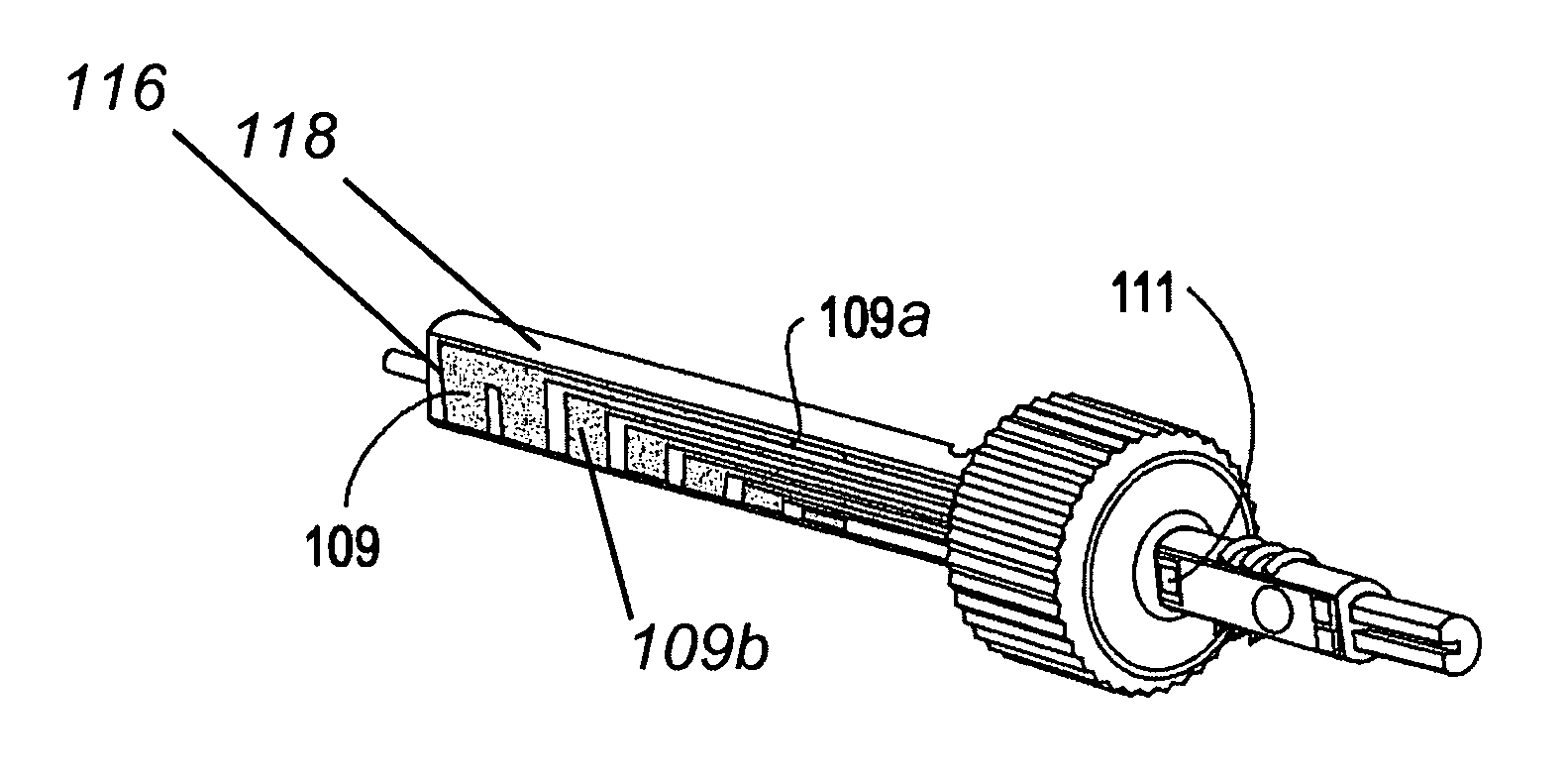
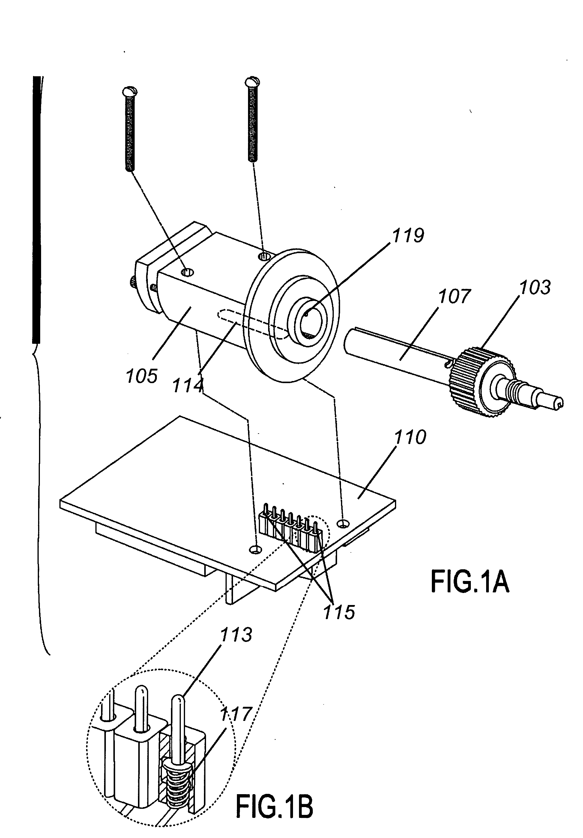
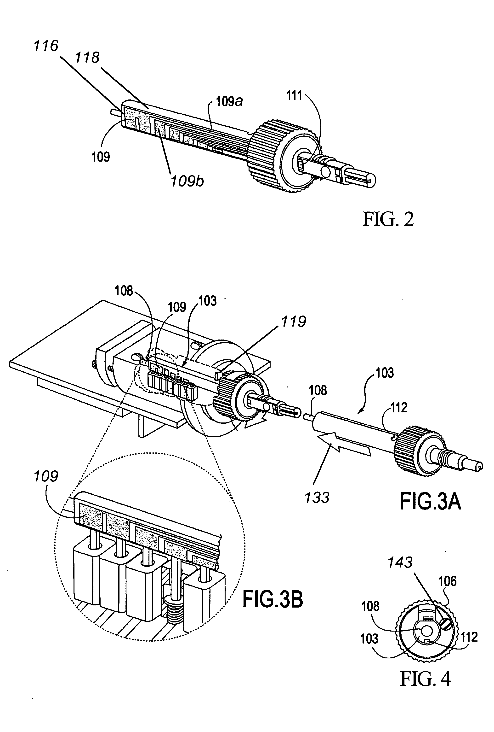
RELATED APPLICATION [0001] This application claims priority to Provisional Patent application Ser. No. 60 / 580,414, filed on Jun. 16, 2004, the disclosure of which is hereby incorporated by reference in its entirety.FIELD OF THE INVENTION [0002] The present invention relates to plug and socket connector systems for providing inexpensive, reversible, axial-position-error tolerant (Z-tolerant) mixed optical and electrical connections, and more particularly to a quick-insertion, non-shorting, rotationally-engaged, shaft and socket connector having one or more Z-tolerant float-coupled optical fibers located centrally inside an elongated shaft, and one or more Z-tolerant wide electrical contact array elements located peripherally on a flexible PC board mounted externally on the same shaft, for the purpose of creating reversible optical / electrical hybrid connections, thus avoiding much of the expense, awkwardness, and required axial precision inherent in conventional hybrid connector syste...

Claims


Application Information

Patent Timeline
IPC IPC(8): G02B6/38
CPCG02B6/3817G02B6/3897H01R13/24H01R13/625H01R24/58H01R2107/00
Inventor BENARON, DAVID A.PARACHIKOV, ILIAN H.FIERRO, MICHAEL R.HUTT, MARVIN K.
Owner J FITNESS LLC
Why Eureka
Try Eureka