Locking button for semi-tractor pneumatics

Inactive Publication Date: 2003-03-06
GUMMERT RANDY A
0 Cites 2 Cited by

AI-Extracted Technical Summary

Problems solved by technology

Many of these devices are costly to make and difficult to install or retrofit into a vehicle.
Although mechanical devices util...

Benefits of technology

0009] An anti-theft device for preventing unauthorized release of the air brakes on a vehicle includes a lockable button for the valve stem for the control valve. The lockable button includes a button body, a coupling member, and a lock assembly having a latch member that selectively inserts into an annular groove on the coupl...

Abstract

An anti-theft device for preventing unauthorized release of the air brakes on a vehicle includes a lockable button for the valve stem for the control valve. The lockable button includes a button body, a coupling member, and a lock assembly having a latch member that selectively inserts into an annular groove on the coupling member. The coupling member is secured to move axially with the axially movable valve stem of the air brake control valve. The latch member extends into the annular groove on the coupling member to position the button body so as to limit the axial movement of the valve stem and thereby prevent the release of the air brakes.

Application Domain

Controlling membersPins +8

Technology Topic

Valve stemAnti theft +3

Image

  • Locking button for semi-tractor pneumatics
  • Locking button for semi-tractor pneumatics
  • Locking button for semi-tractor pneumatics

Examples

  • Experimental program(1)

Example

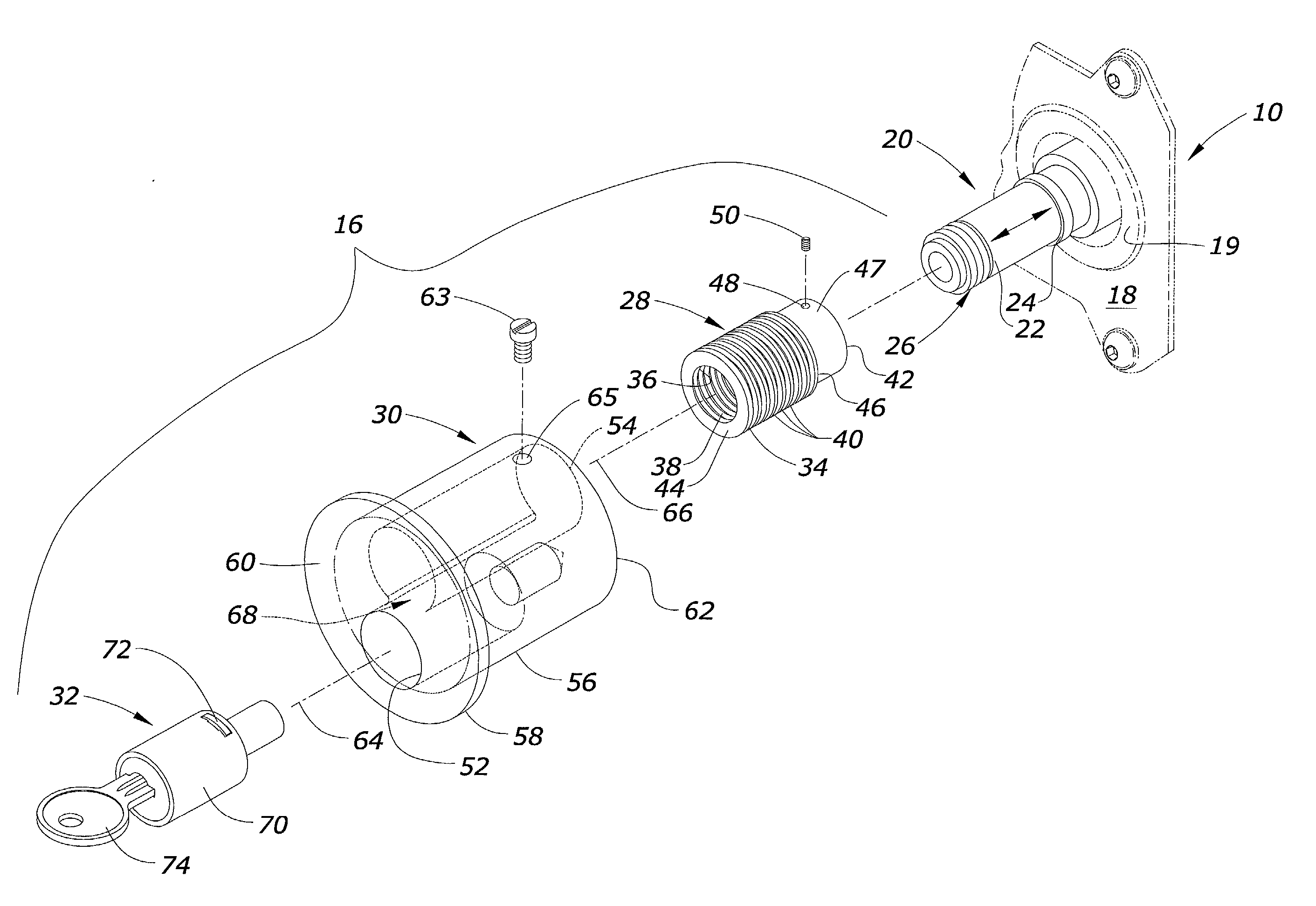
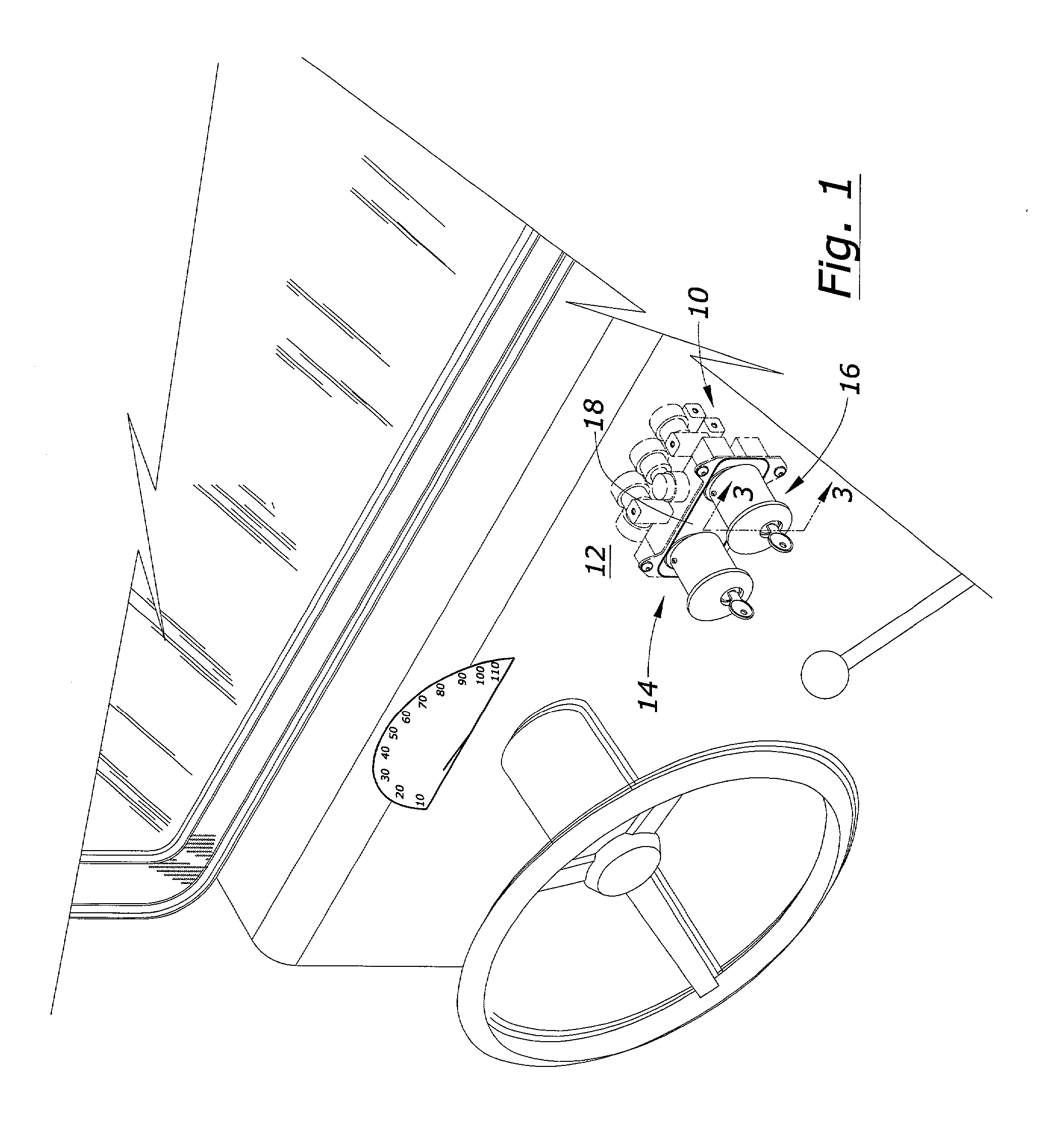
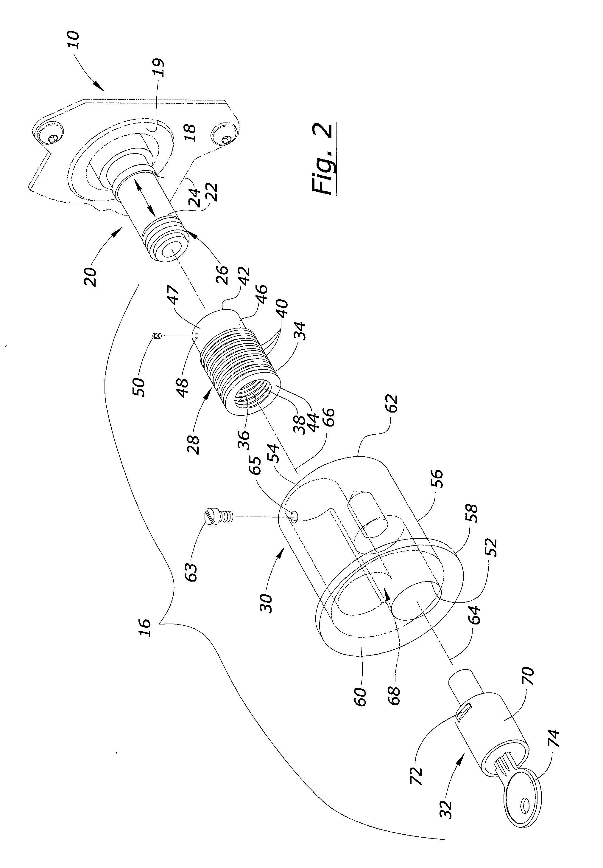
[0016] FIG. 1 illustrates the interior of a cab of a semi-tractor. As is conventional, a pneumatic control valve 10 mounts on or behind the dashboard 12. The control valve 10 controls the air brakes of the semi-tractor and the trailer pulled by the semi-tractor. The present invention provides a lockable button device that replaces the conventional buttons typically found on the air brake control valve 10. For example, when the air brake control valve 10 controls the pneumatics for the semi-tractor and a trailer attached thereto, independently operatable lockable button devices 14, 16 are mounted on the valve 10 respectively. The lockable button devices 14 and 16 are constructed and applied in a substantially identical manner, and thus only lockable button device 16 is described in further detail below.
[0017] Referring to FIG. 2, the air brake control valve 10 has a faceplate 18 and an valve stem 20 that is axially movable with respect to the faceplate 18. Although one skilled in the art will appreciate that it is possible to reverse the logic of the control valve 10, the control valve 10 conventionally releases the air brakes when the valve stem 20 moves toward the faceplate 18, a raised circular pad 19 on the faceplate 18, or an intervening dashboard 12. The semi-tractor or trailer can move once the air brakes are released. Otherwise, the air brakes are normally on and prevent movement of the semi-tractor or trailer. Although it may take other forms depending on the design provided by the control valve manufacturer, the valve stem 20 is generally an elongated rod 22 that includes a shoulder 24 thereon and has means 26 thereon forwarded the shoulder 24 for fastening a conventional button thereto. The means 26 is shown as threads in the present application, but could alternatively include a hole for a roll pin, threaded set screw, or other similar structures.
[0018] The lockable button device 16 includes a coupling member 28, a button body 30, and a lock assembly 32. The coupling member 28 is preferably a cylindrical hollow tubular sleeve that has an outer diameter 34 defining an outer surface and an inner diameter 36 adapted to receive and be secured by fastening means 38, such as threads, to the valve stem 20 to the brake valve 10. The outer diameter or surface 34 of the coupling member 28 includes a groove 40 thereon. More preferably, the outer diameter 34 includes a plurality of annular grooves 40 longitudinally spaced therealong. The coupling member 28 has opposite forward and rearward ends 42, 44 respectively. The coupling member 28 has a reduced diameter portion 47 adjacent the forward end 42 that forms a shoulder between the forward end 42 and the grooves 40. The fastening means 38 optionally includes a hole 48 extending radially into the inner diameter 36 of the coupling member 28. A pin member 50 can be inserted into the hole so as to engage the valve stem 20. In the preferred embodiment shown, the pin member is a threaded set screw, but a roll pin could also be used if a roll pin hole is provided in the valve stem 20.
[0019] The button body 30 has elongated first and second bores 52, 54 therein adapted to receive the lock assembly 32 and the coupling member 28 respectively. The button body includes a substantially cylindrical main body portion 56 and an enlarged head portion 58. The first and second bores 52, 54 are preferably close ended, with the first bore 52 entering at a first end 60 of the body and the second bore 54 entering at a second end 62 of the body. The first bore 52 has a central longitudinal axis 64 that is different from the central longitudinal axis 66 of the second bore. Preferably the central longitudinal axis 64 of the first bore 52 is substantially parallel to the central longitudinal axis 66 of the second bore 54. The button body 30 has an internal cavity 68 that interconnects the first and second bores 52, 54 as shown. Although the internal cavity 68 is shown as a substantially rectangular slot, other shapes will suffice without detracting from the invention.
[0020] The lock assembly 32 is a key lock assembly that includes a substantially cylindrical canister 70 and a latch member 72 that is selectively movable in a transverse direction with respect to the lock canister 70 by turning a key 74. The latch member 72 preferably extends and retracts a radial direction with respect to the lock canister 70. The latch member 72 is elongated and has a substantially rectangular cross section in a transverse plane. As best seen in FIG. 3, the width of the latch member 72 is smaller than the width of the annular grooves 40. Furthermore, the latch member 72 has a convex leading edge residing in a plane transverse to the longitudinal axis of the lock canister 70, so that the latch member 72 is substantially flush with or below the outer surface of the lock canister 70 when retracted. Although it can be rigidly attached in a number of conventional ways, the lock assembly 32 is preferably press fitted into the first bore 52 so as to be frictionally secured to the button body 30. An optional tamper-proof set screw or nonremovable pin can be utilized.
[0021] A screw 63 detachably mounts in the body 30 and extends toward the reduced diameter portion 47 of the coupling member 28 in the second bore 54 forwardly adjacent the shoulder 46. The screw 63 extends through a hole 65 and is adjustable so as to selectively protrude radially into the second bore 54. Thus, the screw 63 prevents the body 30 from being pulled axially from the coupling member 28 because the shoulder 46 cannot move past the protruding screw 63.
[0022] To initially install the lockable button or anti-theft device of this invention, the user first removes any existing conventional button from the valve stem 20. Then the user places the coupling member 28 on the valve stem 20 as shown in FIG. 2, and rotates the coupling member clockwise until the first end 42 abuts or engages the shoulder 24 (FIG. 3). The user can install the optional set screw 50 to prevent the coupling 28 from being loosened. Preferably the factory supplies the button body 30 with the lock assembly 32 already press fitted into the bore 52. The user turns the key 74 clockwise to lower or retract the latch member 72, then installs the button body 30 on the coupling member 28. The user pushes the coupling member 28 into the bore 54 until the latch member 72 registers with one of the grooves 40. The user turns the key 74 counter-clockwise to extend the latch member 72 and lock the button body 30 in a given position on the coupling member 28 and the valve stem 20.
[0023] FIGS. 3 and 4 illustrate that due to the plurality of grooves 40, the button body 30 locks in a number of different positions on the coupling member 28 and the valve stem 20. In FIG. 3, the latch member 72 of the lock assembly 32 fits into one of the grooves 40 that is closer to the rearward end 44 of the coupling member 28. The end 62 of the button body 30 does not abut or engage the raised pad 19 of the faceplate 18 when it is locked to the coupling member 28 in this manner. A gap exists between the button body 30 and the faceplate 18. Thus, the button 16 is in a regular or normal use position wherein the valve stem 20 can be pushed or pulled as needed to release or apply the brakes.
[0024] In FIG. 4, the user has turned the key 74 clockwise and pushed the button body 30 forward on the coupling member 28 until the end 62 abuts or nearly abuts the pad 19 on the faceplate 18. The driver turns the key 74, counter-clockwise to extend the latch member 72 into the nearest groove 40 and lock the body 30 to the coupling member 28 and the valve stem 20. A significant gap no longer exists between the end 62 of the button body 30 and the faceplate 18. Thus, thieves cannot push the valve stem 20 in to release the air brakes and steal the vehicle.
[0025] FIG. 4A shows another possible position of the button body 30, which is useful when the control valve 10 is mounted behind the dashboard 12. The driver again locks the button body 30 in one of the grooves 40 so as to substantially eliminate any gap between the body 30 and the dashboard 12. This prevents the valve stem 20 from being pushed in to release the brakes.
[0026] The grooves 40 on the coupling member 28 are wider than the latch member 72 and are sized and spaced longitudinally along the coupling member 28 so that the device 16 is adaptable to various control valves 10 and control valve mounting arrangements in different makes and models of trucks. Once the button body 30 is in the desired position, the user installs the screw 63 in the hole 65 to retain the button body 30 on the coupling member 28 regardless of whether the latch member 72 of the lock assembly 32 is extended or retracted, i.e.--locked or unlocked. As best seen in FIG. 5, this prevents the inadvertent removal of the button body when it is unlocked. Another unique feature of this invention is that once installed on the coupling member 28, the button body 30 can still be rotated. The annular grooves 40 allow rotation of the button body 30 when the latch member 72 is disposed in one of the grooves 40, and the button body 30 also freely rotates when the latch member 72 is retracted.
[0027] With the lockable button device 16 installed, thieves cannot push the valve stem 20 in to release the air brakes. Thus, the vehicle cannot be moved unless the lockable button devices 14 and 16 are released with appropriate keys 74. An authorized user can use the key 74 to unlock the button body 30 and pull it back. The user reverses the direction of the key 74 to raise the latch member 72 into another groove 40 closer to the rearward end 44 of the coupling member 28. The button body 30 will then be movable axially in both directions like a conventional button.
[0028] Thus, the present invention at least satisfies its stated objectives.
[0029] In the drawings and specifications, there has been set forth a preferred embodiment invention, and although specific terms are employed, these are used in a generic and descriptive sense only and not for purposes of limitation. Changes in the form and proportion of parts as well as in the substitution of equivalents are contemplated as circumstances may suggest or render expedient without departing from the scope of the invention as defined in the following claims.

PUM

no PUM

Description & Claims & Application Information

We can also present the details of the Description, Claims and Application information to help users get a comprehensive understanding of the technical details of the patent, such as background art, summary of invention, brief description of drawings, description of embodiments, and other original content. On the other hand, users can also determine the specific scope of protection of the technology through the list of claims; as well as understand the changes in the life cycle of the technology with the presentation of the patent timeline. Login to view more.

Similar technology patents

Mechanism coupling structure of molded case circuit breaker

ActiveUS20180025876A1reduce pressureprevent release
Owner:LSIS CO LTD

Torque socket

PendingUS20210323126A1rapid connectionprevent release
Owner:CHUANG WEI CHIEH

Silicon wafer heat treatment method

ActiveUS20160130718A1prevent releaseprevent carbon contamination
Owner:SHIN-ETSU HANDOTAI CO LTD

Fixing device for sliding mechanism

ActiveUS20150354752A1prevent release
Owner:JOCHU TECH

Dental composition containing organic nanotube

ActiveUS20110064776A1prevent releasedeterioration in strength
Owner:VERICOM

Classification and recommendation of technical efficacy words

  • prevent release

Assembled peeler

InactiveUS20120085249A1prevent release
Owner:KUAN HUO FENG HSIA

Battery pack

ActiveUS20080286636A1improve assembleabilityprevent release
Owner:SONY CORP

Variable cross-sectioned orthodontic archwire equipped with integrated hook

InactiveUS20170196660A1prevent release
Owner:LINGUALIGN CORP

Ram air turbine blade rotation over-speed prevention mechanism

InactiveUS20060263220A1prevent release
Owner:HAMILTON SUNDSTRAND CORP

Idle speed gpf regeneration

ActiveUS20160201532A1reduces soot loadprevent release
Owner:FORD GLOBAL TECH LLC
Why Eureka
Try Eureka