Flaskless molding machine

a molding machine and flaskless technology, applied in the field of molding machines, can solve the problems of low mold production efficiency, bad factor in the efficiency of mold making of the flaskless molding machine, and the position of the cope flask directly above the drag flask can interfere with an operator, so as to shorten the time required and increase the production efficiency

Active Publication Date: 2008-11-27
SINTOKOGIO LTD
View PDF1 Cites 2 Cited by
  • Summary
  • Abstract
  • Description
  • Claims
  • Application Information

AI Technical Summary

Benefits of technology

[0005]Accordingly, this invention aims to provide a flaskless-molding machine that can shorten the time required for making flaskless molds, and that can increase production efficiency.

Problems solved by technology

Because this situation results in a molding cycle in the conventional flaskless molding machine that still requires much time, the production efficiency of molds is low.
However, in the conventional flaskless molding machine, the cope flask that is located immediately above the drag flask can interfere with an operator who is trying to place the core in the lower mold within the drag flask.
Because the conventional flaskless molding machine provides no ready access to an operator who is trying to place the core in the lower mold, it is also a bad factor in the efficiency of making molds of the flaskless molding machine.

Method used


Image

  • Flaskless molding machine
  • Flaskless molding machine
  • Flaskless molding machine

Examples


Embodiment Construction

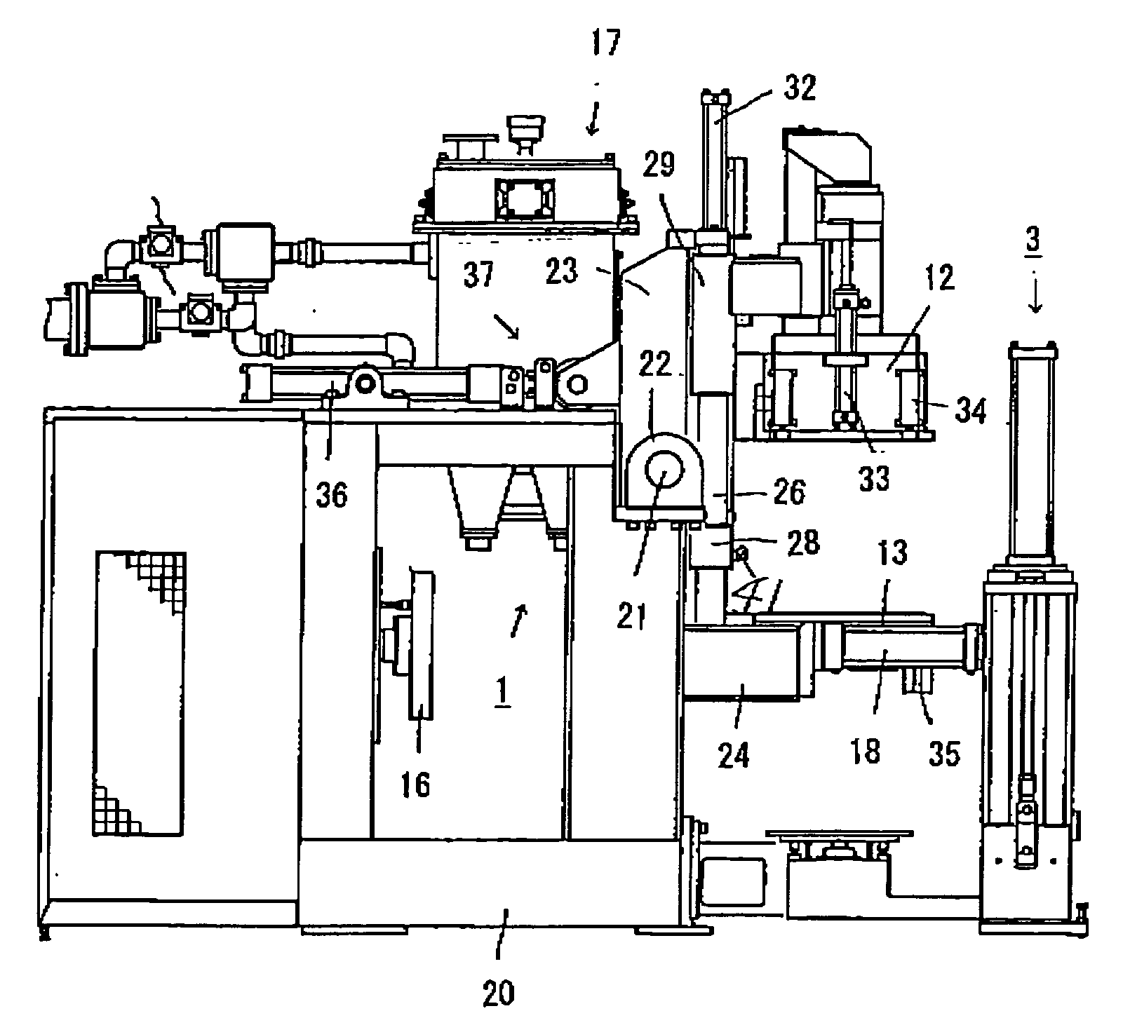
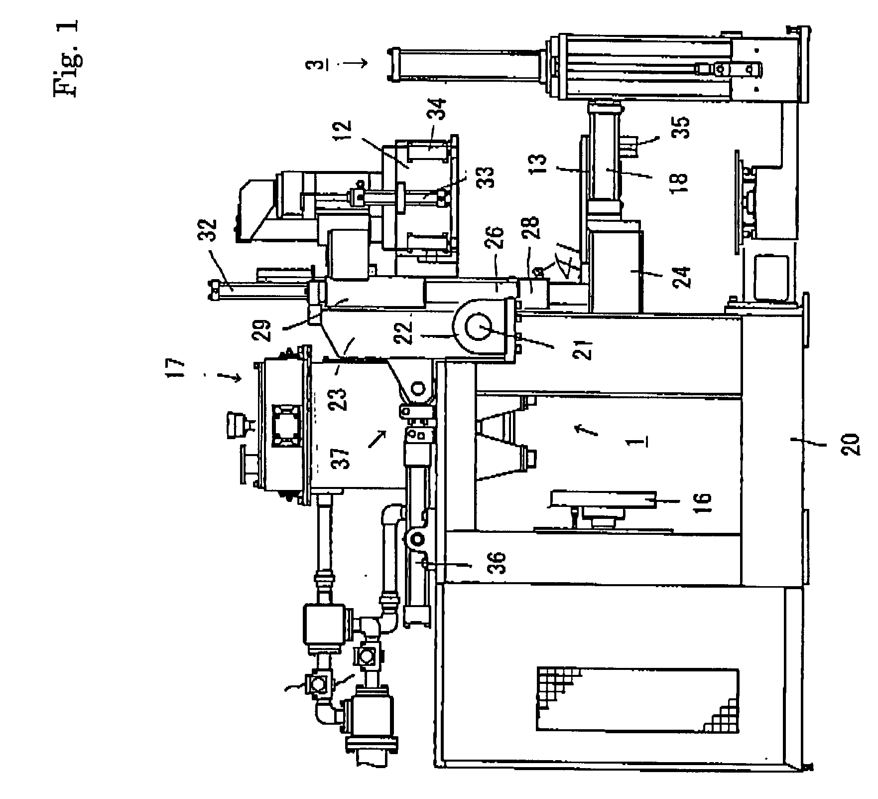
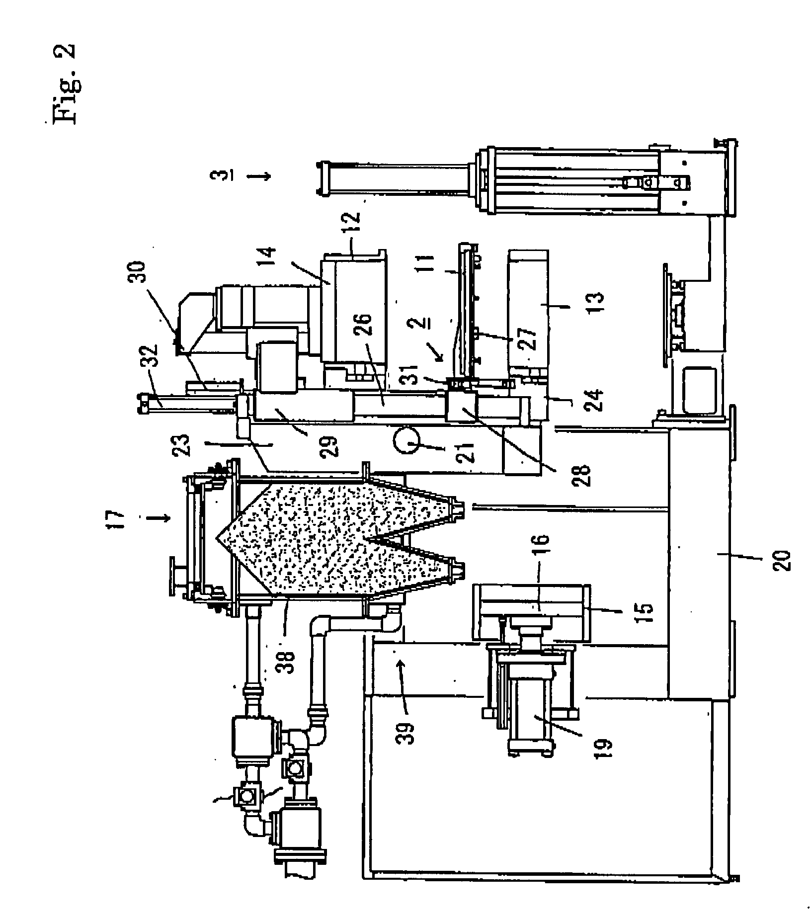
[0025]FIGS. 1 to 4 show one embodiment of the flaskless molding machine of the present invention. The flaskless molding machine generally includes a main unit 1 on a machinery mount 20 of the machine, and a shuttle 2 (FIG. 3) for carrying in and carrying out an exchangeable match plate 11 (FIG. 2) between a cope flask 12 and a drag flask 13 of the main unit 1. The sidewall of each flask 12 or 13 has ports to fill molding sand. Both faces of the match plate 11 are fixed with patterns. The cope flask 12, the drag flask 13, and the match plate 11 that is held therebetween constitute a flask assembly.

[0026]The molding machine in the illustrated embodiment further comprises mold-stripping equipment 3 for stripping the resulting upper and lower molds that are made in the main unit 1 from the cope and the drag flasks 12 and 13.

[0027]1. Main Unit of Molding Machine

[0028]On the molding machine of the present invention, first the main unit 1 of it will be described. As is best shown in FIG. 2...


PUM

PropertyMeasurementUnit
pressureaaaaaaaaaa
molding spaceaaaaaaaaaa
moldingaaaaaaaaaa

Abstract

The disclosed invention provides a molding machine that defines upper and lower molding spaces while cope and drag flasks 12,13 and a match plate 11 clamped therebetween are rotated from a horizontal position to a vertical position, and that readily places a core into a lower mold within the drag flask. An upper squeeze member 14 is insertable into the cope flask 12 with its pressure-applying plane being opposed to the upper face of the match plate 11. The pressure-applying plane defines an upper molding space together with the upper face of the match plate 11 and the cope flask 12. A pivoting frame 23 supports the cope and drag flasks 12,13, a match plate 11 clamped therebetween, and the upper squeeze member 14, such that they rotate in unison between a horizontal position, in which the pressure-applying plane of the upper squeeze member 14 is oriented vertically downward, to a vertical position in which the pressure-applying plane is oriented horizontally. A fixed, vertical, filling frame abuts the drag flask 13 when the flasks 12, 13 and the match plate 11 that is clamped therebetween are in the vertical position. A lower squeeze member 16 has a pressure-applying plane that is oriented horizontally, and is insertable into the filling frame and the abutting drag flask 13. The pressure-applying plane of the lower squeeze member 16 defines a lower molding space together with the lower face of the match plate 11, the drag flask 13, and the filling frame 15. To place a core into a lower mold within the drag flask, the drag flask 13 is laterally moved from a position that is immediately beneath the cope flask 12 such that an open working space is provided.

Description

FIELD OF THE INVENTION[0001]This invention relates to a molding machine, and more particularly, to one to make upper and lower flaskless molds at the same time.BACKGROUND OF THE INVENTION[0002]In the flaskless molding method, an attempt has been made to improve work efficiency by using a well-known flaskless molding machine. For example, Japanese Early-Patent Publication No. 04 [denotes the year 1992]-66245 suggests that a well-known flaskless molding machine be combined with a pattern-changing device. The pattern exchanges mechanically and automatically, rather than manually, for a new pattern plate.[0003]However, the publication describes “the arrangement of the main unit 10 of the molding machine is a well-known one that has been used in a so-called flaskless molding method.” Clearly, the flaskless molding machine employed as in the disclosure is a well-known one that has been used in a conventional flaskless molding method, where the pattern plates are exchanged manually. Theref...

Claims


Application Information

Patent Timeline
Patent Type & Authority Applications(United States)
IPC IPC(8): B22C15/08
CPCB22C9/108B22C11/10B22C7/04B22C17/06B22C21/02
Inventor HIRATA, MINORUKOMIYAMA, TAKAYUKIOYA, TOSHIHIKOSAKAI, TSUYOSHISAKAGUCHI, KOICHI
Owner SINTOKOGIO LTD
Why Eureka
Try Eureka