
Method and apparatus for generating elemental image in integral imaging
a technology of integral imaging and elemental image, applied in the field of generating elemental image, can solve the problems of large amount of time and occurrence of pseudoscopy effect, and achieve the effect of high speed
- Summary
- Abstract
- Description
- Claims
- Application Information
AI Technical Summary
Benefits of technology
Problems solved by technology
Method used
Image

Examples
Embodiment Construction
[0026]The present invention will be described in detail by explaining exemplary embodiments of the invention with reference to the attached drawings.
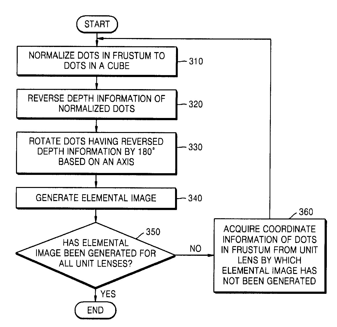
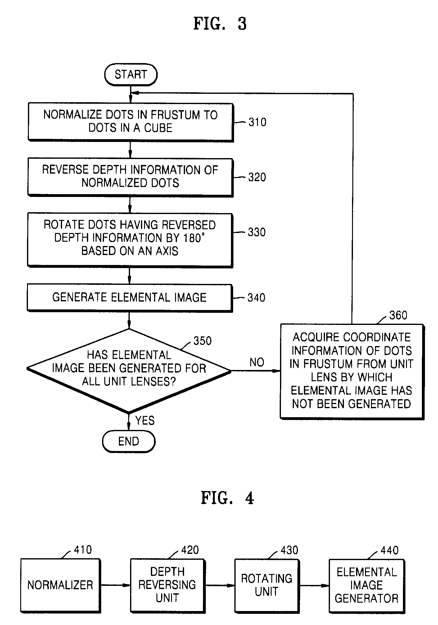
[0027]FIG. 3 is a flowchart of a method of generating an elemental image according to an exemplary embodiment of the present invention.
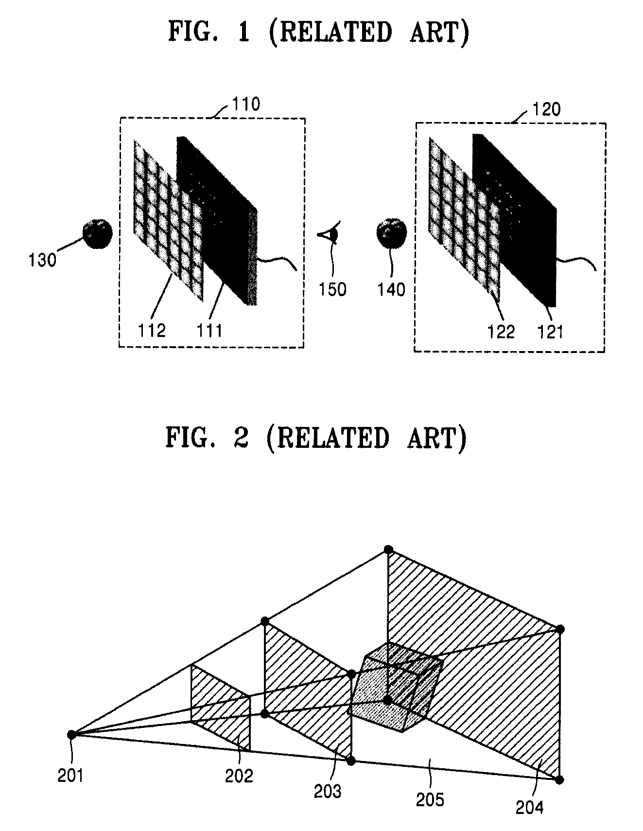
[0028]In operation 310, an apparatus for performing the method of generating an elemental image normalizes coordinates of dots in a frustum illustrated in FIG. 5 by mapping coordinate information of the dots in the frustum to coordinate information of dots in a cube.
[0029]The normalization is performed using Equation 1.
(x′y′z′w′)=(fr0000fr0000100001)(xyzw)x′=frxy′=fryz′=z(Equation1)
[0030]Here, referring to FIG. 5, −f denotes z-axis boundary coordinates of a rear-end plane of a frustum, r denotes x-axis boundary coordinates in the right of the rear-end plane of the frustum, and t denotes y-axis boundary coordinates in the top of the rear-end plane of the frustum.
[0031]In operation 320, the apparatus for p...
PUM
 Abstract
Description
Claims
Application Information