Power receiving device, and electronic apparatus and non-contact charger using the same

a technology of power receiving device and charger, which is applied in the direction of electrochemical generators, safety/protection circuits, magnetic bodies, etc., can solve the problems of defective charging, reduced weight of electronic devices, limited secondary battery capacity, etc., and achieves the effect of reducing charging efficiency and suppressing heat generation

Active Publication Date: 2009-03-05
KK TOSHIBA +1
View PDF14 Cites 106 Cited by
  • Summary
  • Abstract
  • Description
  • Claims
  • Application Information

AI Technical Summary

Benefits of technology

[0015]According to an aspect of the present invention, there are provided a power receiving device which can suppress heat generation due to an eddy current and a decrease in charging efficiency by suppressing the eddy current generated in the power receiving side by electromagnetic induction, and an electronic apparatus and a non-contact charger using the same.

Problems solved by technology

But, the capacity of the secondary battery is limited, and it is required to recharge once per several days to several weeks.
But, the weight of the electronic apparatus has been reduced with the downsizing and weight reduction of the electronic apparatus in these years, and the contact pressure between the electrode of the power receiving device and the electrode of the power feeding device becomes insufficient, causing a problem of defective charging.
Conventional non-contact charging methods mainly use a nickel-hydrogen battery as a secondary battery and therefore many of them have a disadvantage that their charging time is about eight hours.
But, the ferrite becomes brittle and has poor impact resistance when it is fabricated into a thin form, and the power receiving device tends to have a malfunction if the equipment is dropped.
Therefore, there is a problem that high electric power cannot be transmitted, and a charging time becomes long as a result.
For example, when the power transmission speed is increased without regard to heat generation, it is worried that carbon dioxide is produced within the Li ion secondary battery to expand and rupture it.
Therefore, when it is intended to increase a power transmission speed by the non-contact charging method, a problem of heat generation due to the eddy current is nonnegligible.
Thus, a power receiving device applying a conventional non-contact charging method is insufficient to take measures against the eddy current generated due to the electromagnetic induction and against heat generation due to the eddy current.
The generation of the eddy current leads to the generation of noise and also becomes a factor for lowering the charging efficiency.

Method used


Image

  • Power receiving device, and electronic apparatus and non-contact charger using the same
  • Power receiving device, and electronic apparatus and non-contact charger using the same
  • Power receiving device, and electronic apparatus and non-contact charger using the same

Examples


example 1

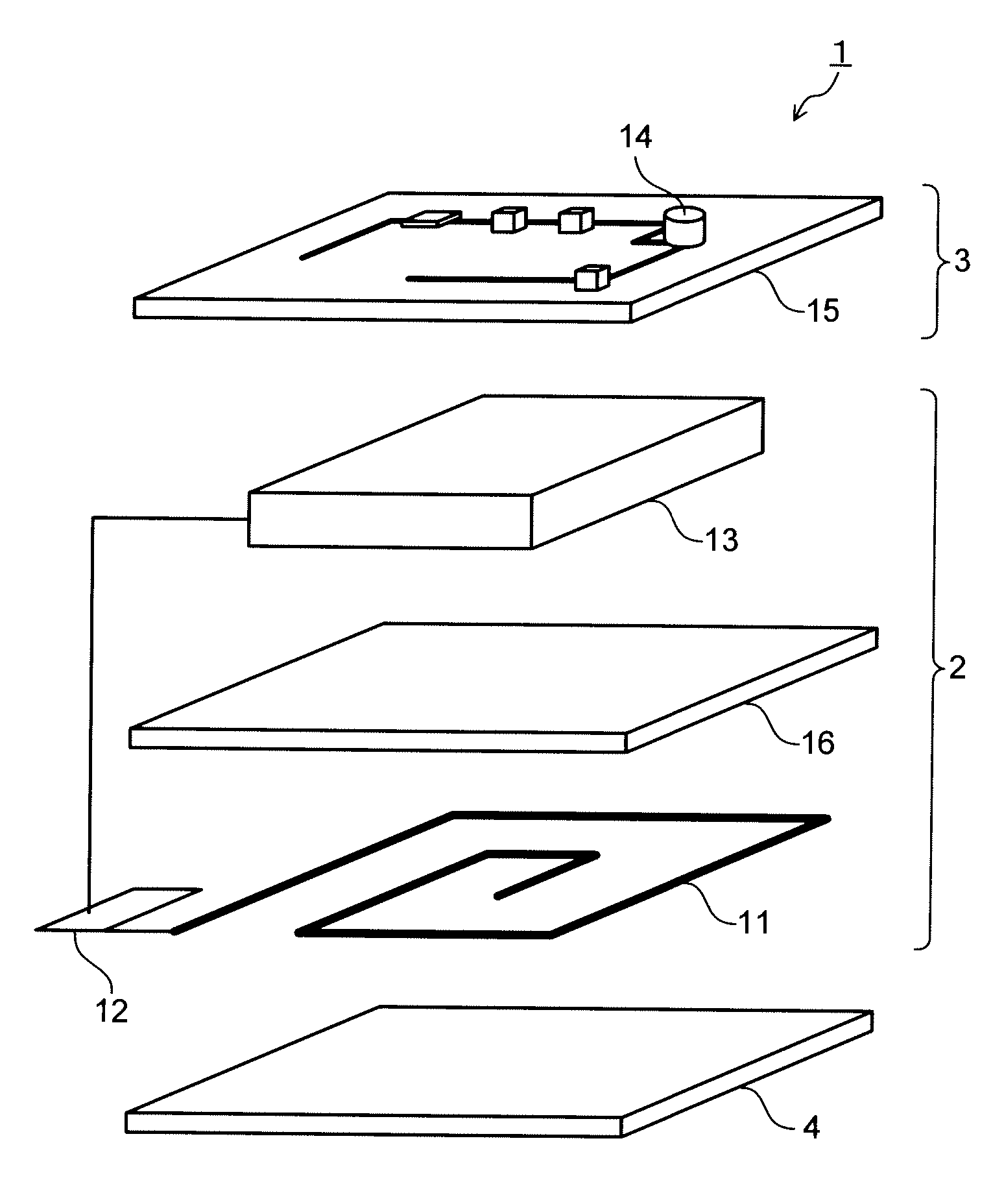
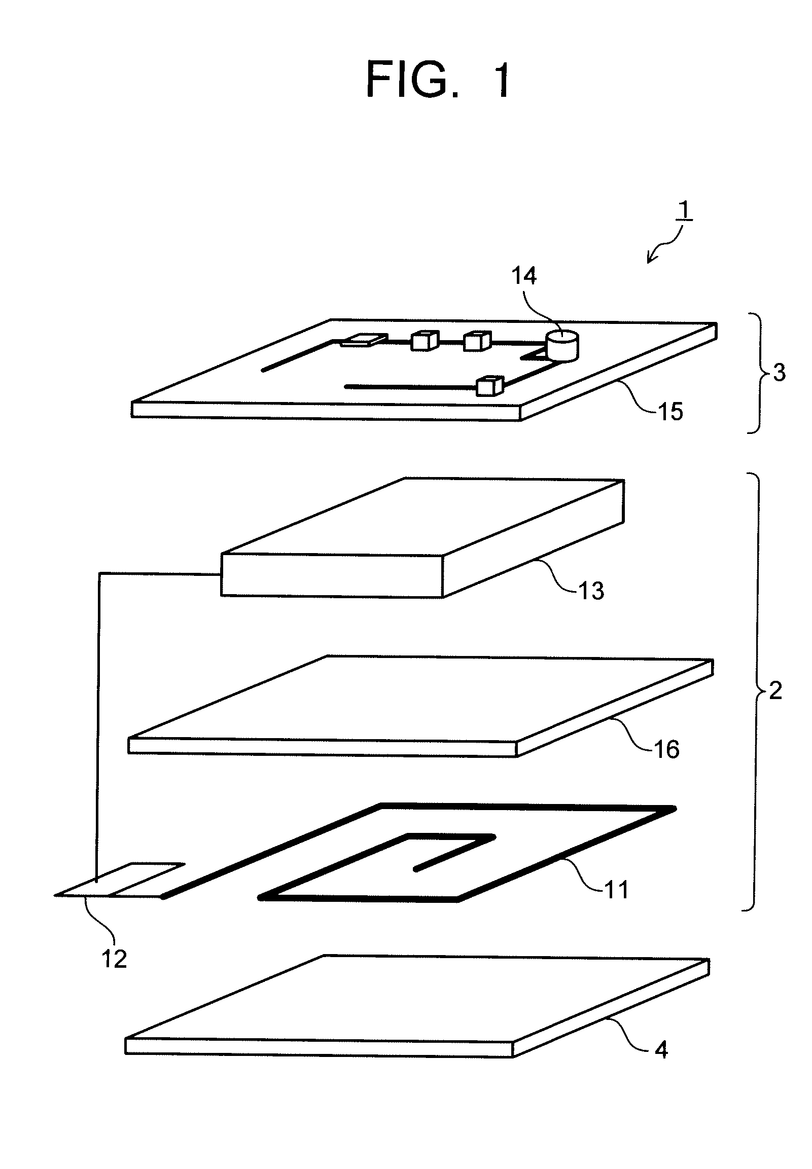
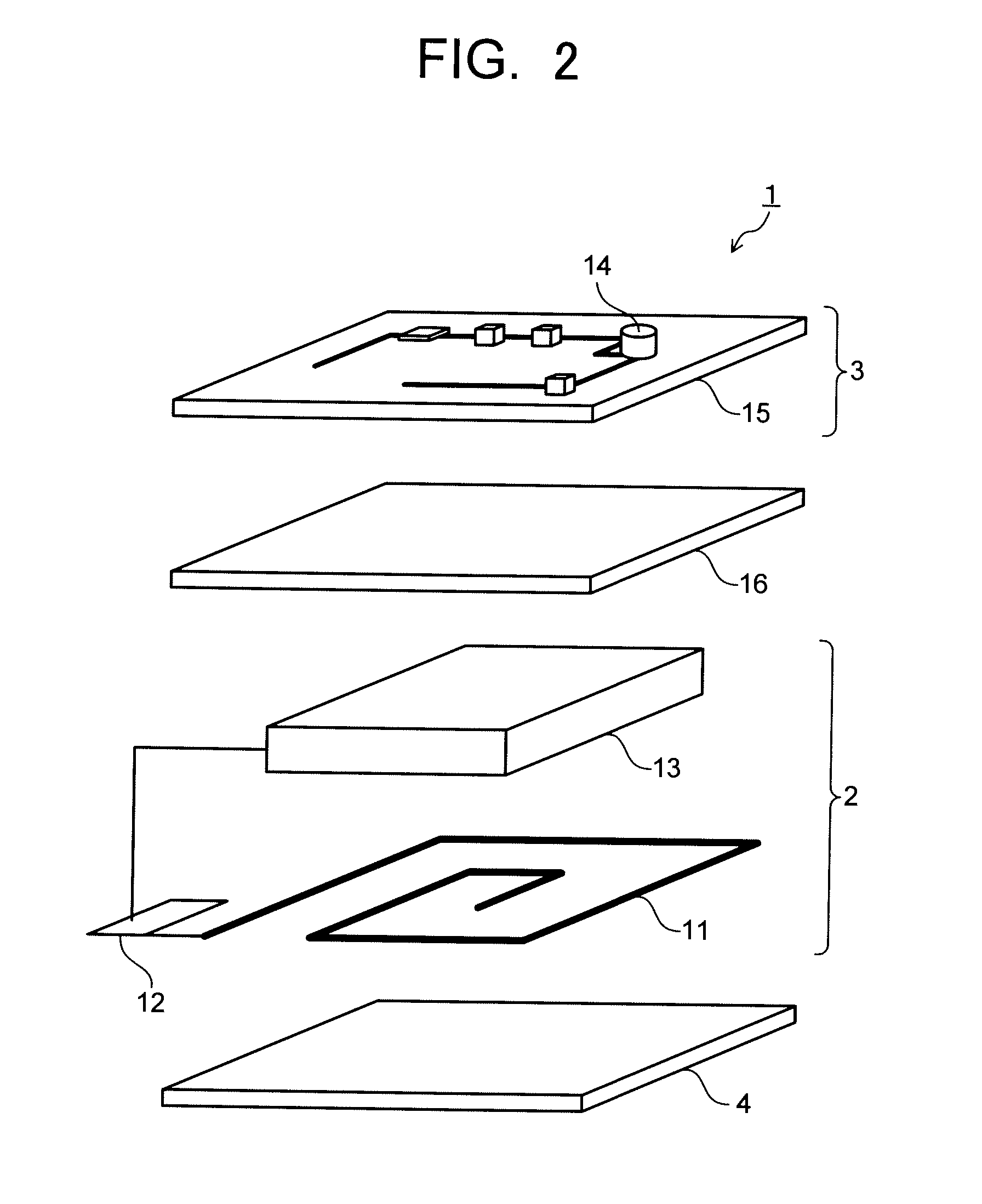
[0102]As a magnetic foil, an amorphous alloy ribbon having a saturation flux density Ms of 0.55, a real component μr′ of 18000 of a relative permeability, an average thickness of 9.5 μm, and a composition of CO70Fe5Si5B20 (atomic ratio) was prepared. The amorphous alloy ribbon was heat treated under conditions of 440° C.×30 min. The amorphous alloy ribbon had a shape that a protruded amount do of an outer peripheral portion was 6 mm. Three of the amorphous alloy ribbons were stacked and disposed between the secondary coil (power receiving coil 11) and the secondary battery 13 as shown in FIG. 1. A cellular phone and a non-contact charger using a power receiving device having the above magnetic foil were determined as Example 1.

examples 2 and 3

[0103]Power receiving devices were configured in the same manner as in Example 1 using the amorphous alloy ribbon having the same composition as in Example 1, except that the heat treatment conditions, the average thickness and the stacked number were changed to the conditions shown in Table 1. Cellular phones and non-contact chargers using the above power receiving devices were determined as Examples 2 and 3.

examples 4 to 7

[0104]As a magnetic foil, an amorphous alloy ribbon having a composition of Fe78Si8B14 (atomic ratio) was prepared. The heat treatment conditions, the average thickness, the stacked number of the amorphous alloy ribbons are as shown in Table 1. Power receiving devices were configured in the same manner as in Example 1, except that the obtained amorphous alloy ribbons were used. Cellular phones and non-contact chargers using the above power receiving devices were determined as Examples 4 to 7.


PUM

PropertyMeasurementUnit
charging timeaaaaaaaaaa
thicknessaaaaaaaaaa
alternating voltageaaaaaaaaaa

Abstract

Disclosed is an electronic apparatus (1) comprising a power receiving device (2) and an electronic apparatus main body (3). The power receiving device (2) comprises a power receiving coil (11) having a spiral coil, a rectifier (12) and a secondary battery (13). The electronic apparatus main body (3) comprises an electronic device (14) and a circuit board (15). A magnetic foil (16) is arranged in at least one position between the spiral coil (11) and the secondary battery (13), the rectifier (12), the electronic device (14) or the circuit board (15). The magnetic foil (16) has a value expressed as the product of the saturation flux density MS and the thickness t, namely Ms·t, of not less than 15.

Description

TECHNICAL FIELD[0001]The present invention relates to a power receiving device which is applied to non-contact charging, and an electronic apparatus and a non-contact charger using the same.BACKGROUND ART[0002]The development of portable telecommunication equipments is remarkable in these years, and especially cellular phones are being made smaller and lighter quickly. In addition to the cellular phones, electronic apparatuses such as handy cameras (portable video cameras etc.), cordless telephones, laptop PCs (notebook PCs) and the like are also being made smaller and lighter. They have a secondary battery provided within an electronic apparatus main body so as to be usable without connection to a wall outlet. Thus, their portability and usability are enhanced. But, the capacity of the secondary battery is limited, and it is required to recharge once per several days to several weeks.[0003]Recharging methods include a contact charging method and a non-contact charging method. The c...

Claims


Application Information

Patent Timeline
Patent Type & Authority Applications(United States)
IPC IPC(8): H02J7/00H01F1/147H01F1/153H01F1/16H01F27/36H01F38/14
CPCH01F10/131H01F17/0006H01F27/365H02J7/025H01F2027/348H01M10/46H01Q1/248H01F38/14H02J50/10H02J7/00302H02J50/70H01F27/36Y02E60/10H01F27/366
Inventor INOUE, TETSUOKUSAKA, TAKAO
Owner KK TOSHIBA
Why Eureka
Try Eureka