Wireless telecommunications network adaptable for patient monitoring

a technology of patient monitoring and wireless telecommunications network, which is applied in the direction of machine-to-machine/machine-type communication services, instruments, applications, etc., can solve the problem that all the prior art systems are not particularly suitabl

Inactive Publication Date: 2009-04-23
SMITHS MEDICAL ASD INC
View PDF45 Cites 49 Cited by
  • Summary
  • Abstract
  • Description
  • Claims
  • Application Information

AI Technical Summary

Benefits of technology

[0007]The present invention, among its multiple aspects which may themselves constitute self standing inventions, attempts to overcome the need for a central server or hub to which the data collected from the patient is routed, per taught by the prior art. The present invention therefore aims to, in the one aspect, provide remote monitoring across a network, for example a peer-to-peer network or a mesh network with a deterministic configuration, so that there is no reliance on a single hub or access point.
[0008]The present invention, in one aspect, more particularly relates to a wireless communications network that is adapted for use by medical devices and that has an architecture that may be in the form of a peer-to-peer network of medical devices without a network controller. Each of the medical devices may be considered a node of the network, with the medical devices or nodes being time synchronized and the communications among the devices scheduled, to thereby eliminate in network interference and allow good quality both in terms of the communications among the nodes and the types of messages disseminated among the devices.

Problems solved by technology

Yet all of these prior art system are not particularly suited to the above mentioned hospital environment in which there is a need to provide mobility for the patients, as well as the need to monitor the multiple patients.

Method used


Image

  • Wireless telecommunications network adaptable for patient monitoring
  • Wireless telecommunications network adaptable for patient monitoring
  • Wireless telecommunications network adaptable for patient monitoring

Examples


Embodiment Construction

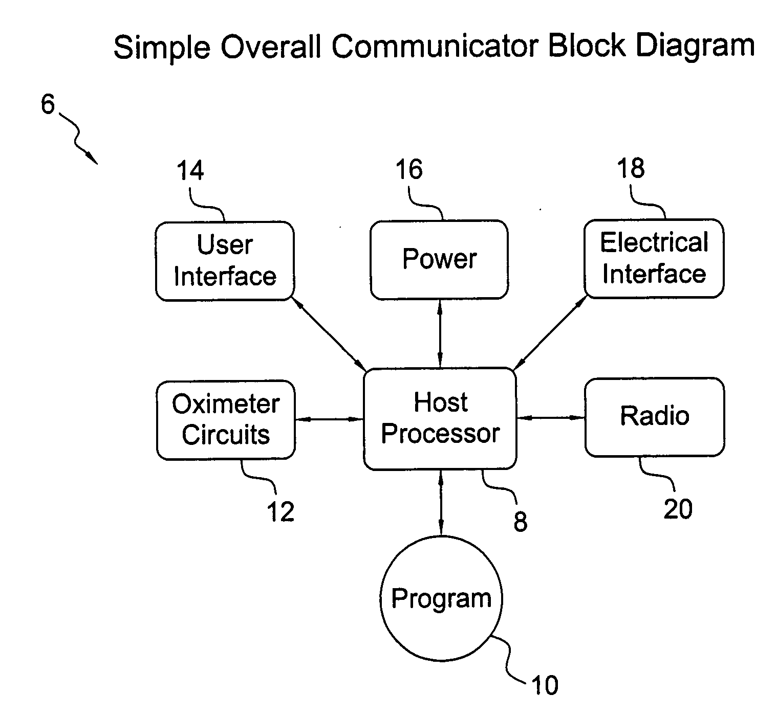
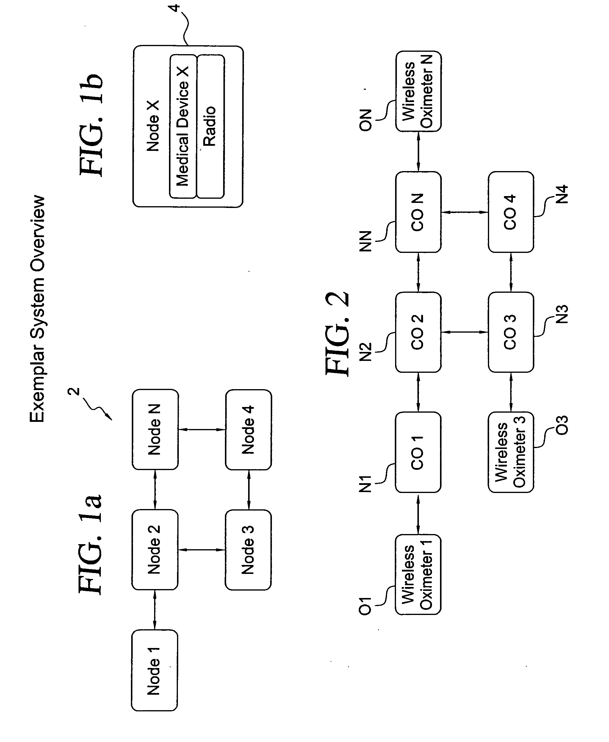
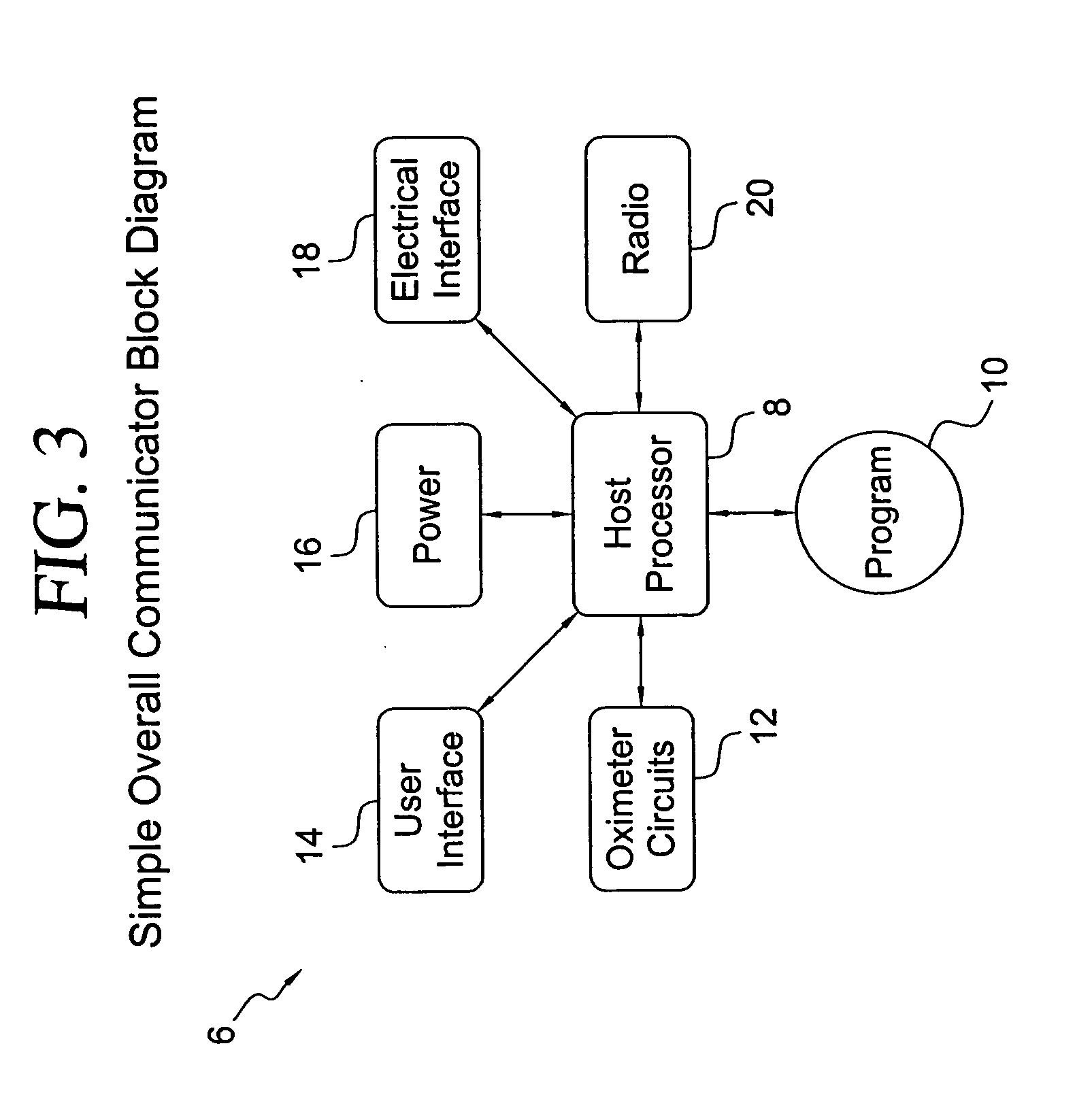
[0051]With reference to FIGS. 1a and 1b, a communications network, in the configuration for example of a peer-to-peer network, is shown. For the exemplar wireless network 2 shown in FIG. 1a, there are four nodes 1-4, as well as a node N that signifies that the network can have N number of nodes. For the embodiment of the invention shown in FIG. 1a, it is presumed that each of the nodes shown may be represented by node 4 of FIG. 1b in that each of the nodes of the network may be a medical device that includes a radio, which may be a transmitter or transceiver. The medical device may be any one of a number of devices that monitor or measure physical attributes or parameters of a patient or subject. Such medical devices include, but are not limited to, oximeters, heart rate monitors, capnographs or CO2 monitors, pumps that connect to the patient and other devices that monitor particular physical attributes of a patient. For example, in the case of a pulse oximeter, the oxygen level of ...


PUM


Abstract

A wireless network having an architecture that resembles a peer-to-peer network has two types of nodes, a first sender type node and a second receiver / relay type node. The network may be used in a medical instrumentation environment whereby the first type node may be wireless devices that could monitor physical parameters of a patient such as for example wireless oximeters. The second type node are mobile wireless communicators that are adapted to receive the data from the wireless devices if they are within the transmission range of the wireless devices. After an aggregation process involving the received data, each of the node communicators broadcasts or disseminates its most up to date data onto the network. Any other relay communicator node in the network that is within the broadcast range of a broadcasting communicator node would receive the up to date data. This makes it possible for communicators that are out of the transmitting range of a wireless device to be apprized of the condition of the patient being monitored by the wireless device. Each communicator in the network is capable of receiving and displaying data from a plurality of wireless devices.

Description

FIELD OF THE INVENTION [0001]The present invention relates to a wireless telecommunications network that may be used in the medical industry, and more particularly relates to a nodal network that has a plurality of node communicators for conveying patient parameters remotely from the site where the patient is being monitored. Also disclosed are inventions that relate to the method of remotely conveying or propagating patient information along the network and the devices used in such wireless telecommunications network.BACKGROUND OF THE INVENTION [0002]To remotely monitor physical parameters, for example blood pressure, arterial oxygen blood saturation (SP02), heart rate, electrocardiogram, etc., of a patient, a sensor is usually attached to the patient, with the sensor being connected to a transmitter that transmits the patient signals to a central nursing station. Such transmission is usually by hardwire, and more recently wirelessly. At the nursing station, which may either be loc...

Claims


Application Information

Patent Timeline
Patent Type & Authority Applications(United States)
IPC IPC(8): A61B5/1455G08B1/08H04W4/70
CPCG06F19/3406A61B5/002G06F19/3418H04W84/18G16H40/63H04W4/70G16H40/67
Inventor SMITH, GUY A.OSWALD, MATTHEW T.BROWN, MATTHEW L.ELLIS, MATTHEW W.
Owner SMITHS MEDICAL ASD INC
Why Eureka
Try Eureka