Conveyor

a conveyor and belt technology, applied in the direction of conveyor parts, rollers, transportation and packaging, etc., can solve problems such as belt movemen

Inactive Publication Date: 2009-07-02
MURATA MASCH LTD
View PDF6 Cites 5 Cited by
  • Summary
  • Abstract
  • Description
  • Claims
  • Application Information

AI Technical Summary

Benefits of technology

[0009]When the detection roller is pressed by the belt, the corresponding cam below the rear face of the belt may be shifted to the right or left to incline the correction roller by combining the cam face inclined upward from the right or left end toward the center of the belt with the supporting member of the correction roller that is lifted along the inclined face of the cam. This configuration requires no motor to drive the correction roller. Accordingly, a meandering corrector is provided that promptly and surely responds to meandering and causes less malfunction. In addition, the cams may be attached slidably to right and left to a frame that extends from right to left below the rear face of the belt, and the lower ends of the support rods of the detection rollers may be attached to the cams. Biasing members may be provided that bias the cams toward the center of the rear face of the belt. In this configuration, when one of the detection rollers is pressed by the belt and is shifted, the corresponding cam is surely shifted and the corresponding correction roller is regulated to be inclined in accordance with the degree of meandering of the belt.

Problems solved by technology

Belt conveyors sometimes have a problem during operation in that horizontal misalignment of the belt and the like results in meandering of the belt.
However, this technique requires a large mechanism including the sensor that detects horizontal misalignment and the motor for meandering correction.

Method used


Image

  • Conveyor
  • Conveyor
  • Conveyor

Examples


Embodiment Construction

[0015]Embodiments of the present invention are described below.

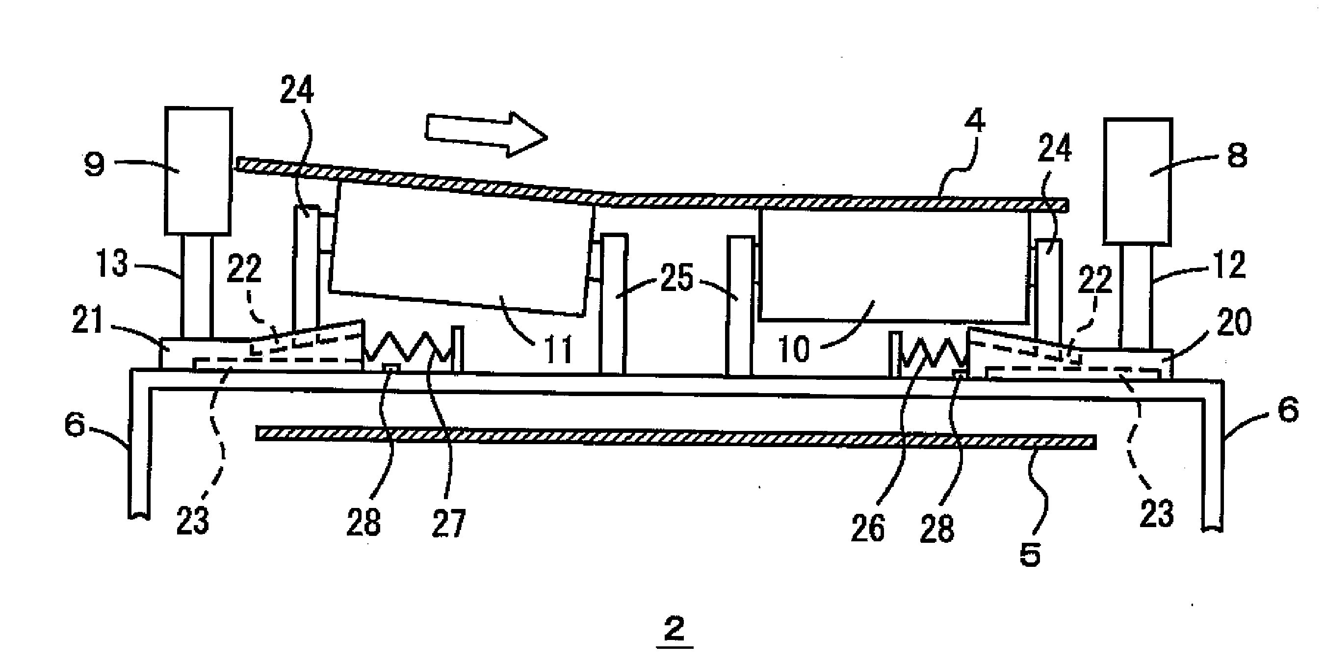
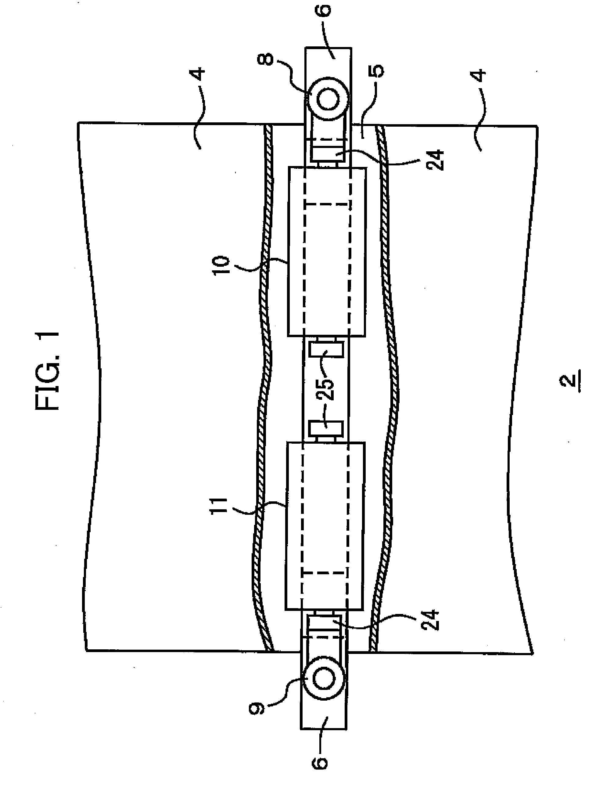
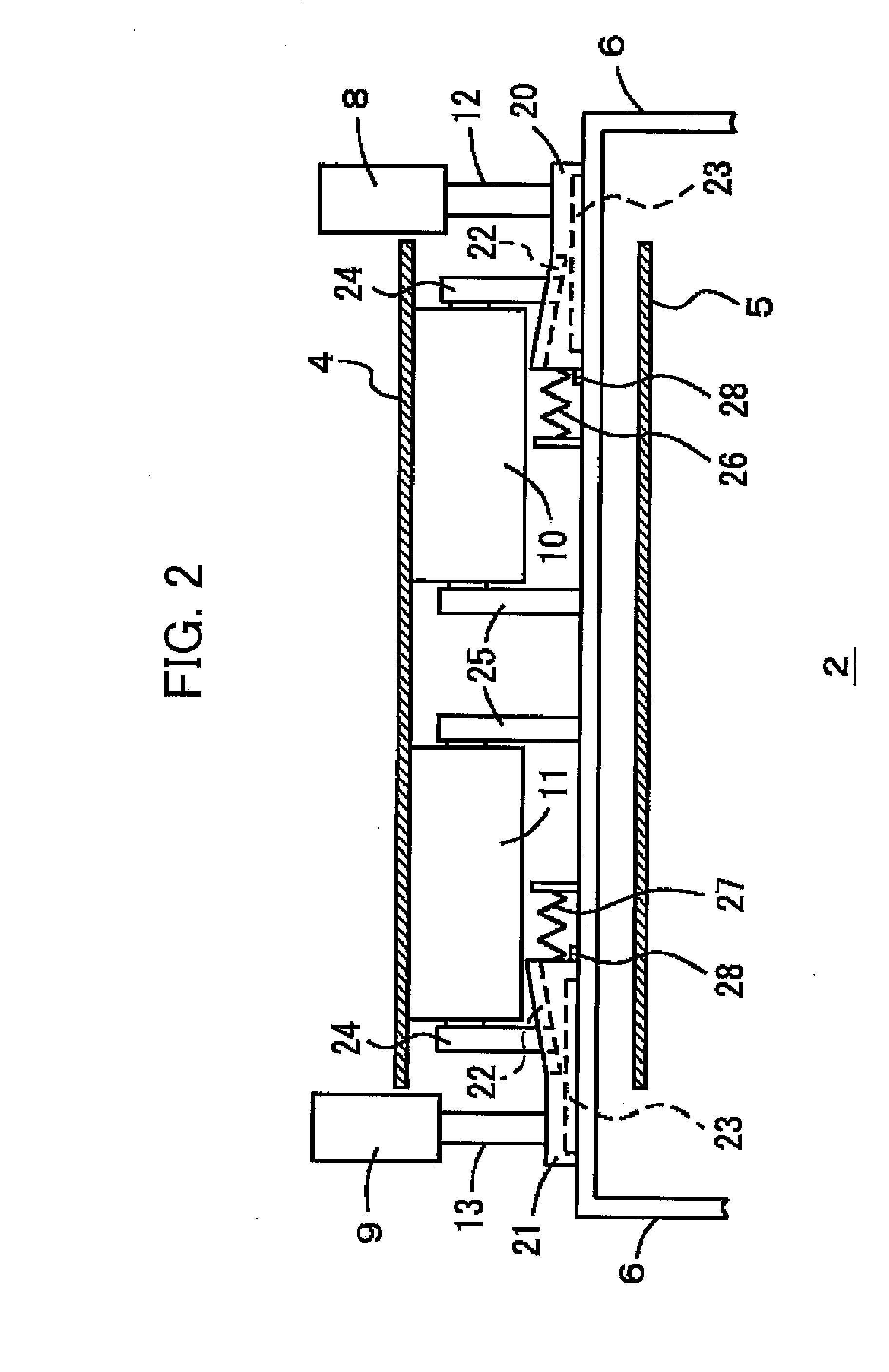
[0016]FIGS. 1-4 illustrate a belt conveyor 2 according to embodiments of the invention. The belt conveyor 2 includes an outgoing belt 4 and a returning belt 5, each made of steel, rubber, or the like. A steel belt is particularly suitable for the present invention, as a meandering steel belt creates a dangerous situation. In this specification, right and left indicate directions orthogonal to traveling directions of the belts 4 and 5 in a horizontal plane, and belts 4 and 5 travel in, for example, a horizontal direction (up-and-down direction of FIG. 1, for example).

[0017]A frame 6 extending from right to left is interposed between the outgoing belt 4 and the returning belt 5, and a pair of detection rollers 8 and 9 are disposed outside right and left ends of the outgoing belt 4. A pair of right and left correction rollers 10 and 11 are provided to be in contact with a rear face of the outgoing belt 4. Support rods 12 an...


PUM


Abstract

A belt conveyor includes right and left detection rollers outside ends in a width direction of a belt. Right and left correction rollers are disposed on right and left sides on a rear face of the belt. When one of the detection rollers is pressed by the belt, the corresponding correction roller is inclined from the pressed detection roller down to a center of the belt, thereby correcting the meandering belt.

Description

CROSS-REFERENCE TO RELATED APPLICATIONS[0001]This application claims the benefit of priority under 35 USC 119 of Japanese patent application no. 2007-340150, filed on Dec. 28, 2007, which is incorporated herein by reference.BACKGROUND OF THE INVENTION[0002]1. Field of the Invention[0003]The present invention relates to a belt conveyor, and particularly relates to correction of a meandering belt.[0004]2. Description of the Related Art[0005]Belt conveyors sometimes have a problem during operation in that horizontal misalignment of the belt and the like results in meandering of the belt. In order to correct the meandering belt, applicant previously proposed a technique of detecting horizontal misalignment of the belt with a sensor and lifting up a meandering correction roller with a motor (Refer to Japanese Unexamined Utility Model Application No. H01(1989)-58517). However, this technique requires a large mechanism including the sensor that detects horizontal misalignment and the motor...

Claims


Application Information

Patent Timeline
Patent Type & Authority Applications(United States)
IPC IPC(8): B65G39/16
CPCB65G39/16
Inventor MURAYAMA, HIROSHI
Owner MURATA MASCH LTD
Why Eureka
Try Eureka