
Neutron-optical component array for the specific spectral shaping of neutron beams or pulses

a technology of neutron beams or pulses and neutron optical components, applied in the direction of lasers, instruments, electromechanical components, etc., can solve the problems of limited flexibility and structural restraints in the modulator combination, and achieve the effect of low cost, simple structure and operation, and relatively few malfunctions

Inactive Publication Date: 2006-04-18
HAHN MEITNER INSTITUT FUR KERNFORSCHUNG BERLIN
View PDF5 Cites 5 Cited by
  • Summary
  • Abstract
  • Description
  • Claims
  • Application Information

AI Technical Summary

Benefits of technology

[0009]For that reason, it is an object of the invention to provide an array of neutron-optical components for the specific shaping of the spectrum of a neutron beam of the kind referred to supra which offers significant flexibility in respect of providing one neutron beam to one place of experiment, so that no extensive structural changes are required in case of change requirements. More particularly, experiments with neutrons from a larger energy range are to be made possible as well. Furthermore, the neutron beam provided by the invention is to be of high quality. The means for realizing the invention are to be simple in their structure and operation and, therefore, subject to relatively few malfunctions as well as low costs. Present aspects of safety are to be taken into consideration and additional risks are to be avoided.BRIEF SUMMARY OF THE INVENTION
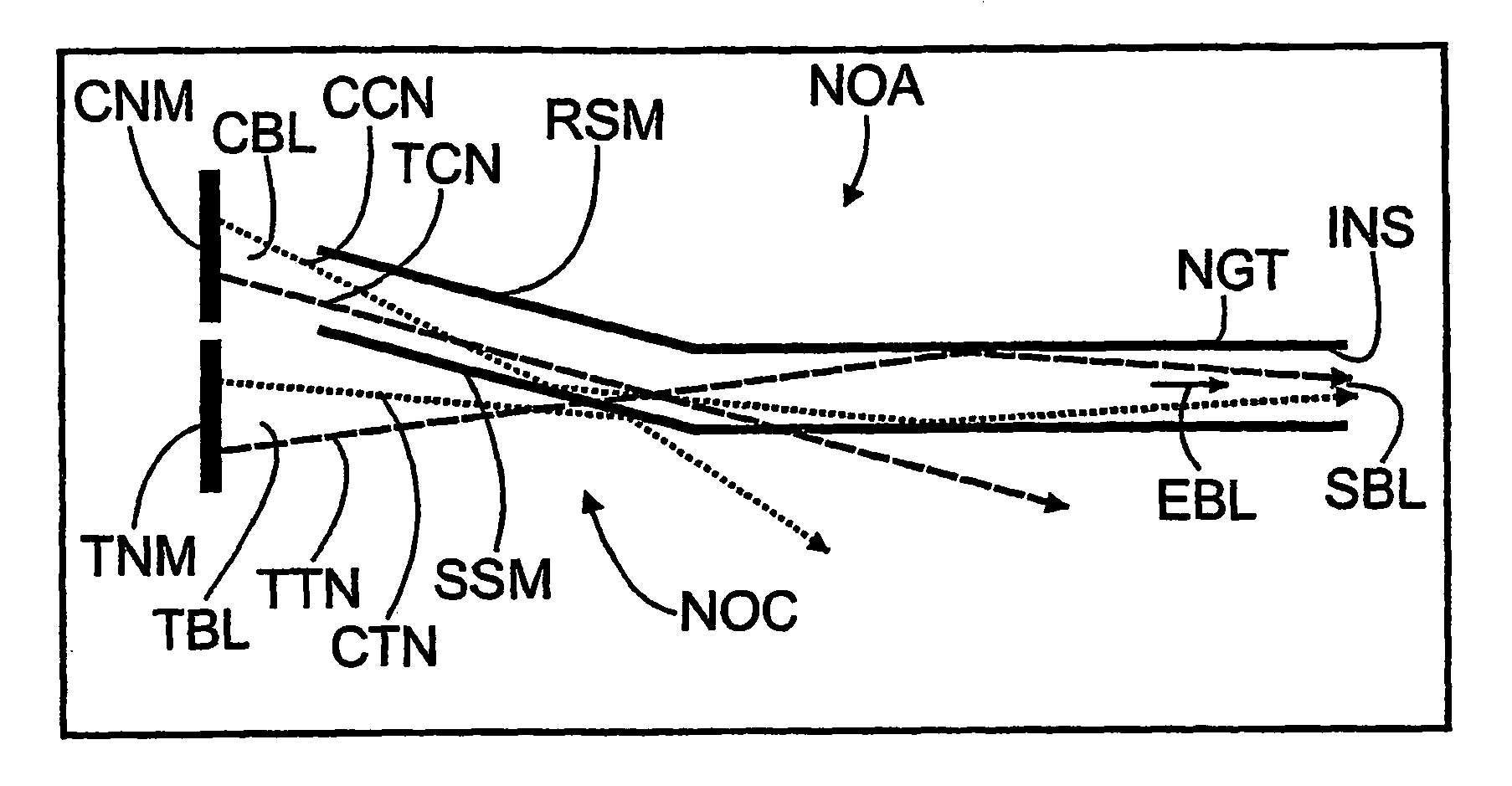
[0012]The overlapping of the individual neutron beams from the moderators used to a common neutron beam may take place in the neutron guide as well at the place of experimenting. The first case results in the formation of a neutron beam which like a single electron beam is conducted in one neutron guide to the place of experiment and to the probe. In the second case, the different neutron beams are focused on the probe to be examined so that the overlapping neutron beam impinges directly on the probe. The advantage of this overlapping irradiation at the place of experiment itself resides in the relatively low technical complexity for combining the directions of radiation of the individual moderators. In the simplest case, the adjacent moderators are to be arrayed relative to each other at such angles that it results in a focal point of the radiation directions in the probe or slightly in front thereof. In a further development of the neutron-optical component array in accordance with the invention the radiation directions may, in case they overlap directly, be detectable at the place of experiment by a predetermined encoding scheme. In terms of the measurement results it may be important to know the different radiation directions from which the different kinds of neutrons impinge upon the probe. In a pulsed neutron source this may be carried out by monitoring the neutron flight time. In case of a it is necessary to chop the neutron beam correspondingly. Since within the slow neutrons, the cold, thermal, and hot neutron differ by the energy spectrum and, hence, by their velocity distribution, knowledge of the individual neutron flight times makes possible, on the basis of the pulses, an association to the individual moderators and, therefore, with their radiation direction relative to the probe.

Problems solved by technology

The combination of different modulators is limited only by structural restraints since in terms of apparatus technology the combination of the radiation direction must be realizable with a reasonable effort.
The disadvantage of the low flexibility was accepted and corresponding numbers of places of experiment were conceived.

Method used


Image

  • Neutron-optical component array for the specific spectral shaping of neutron beams or pulses
  • Neutron-optical component array for the specific spectral shaping of neutron beams or pulses

Examples


Embodiment Construction

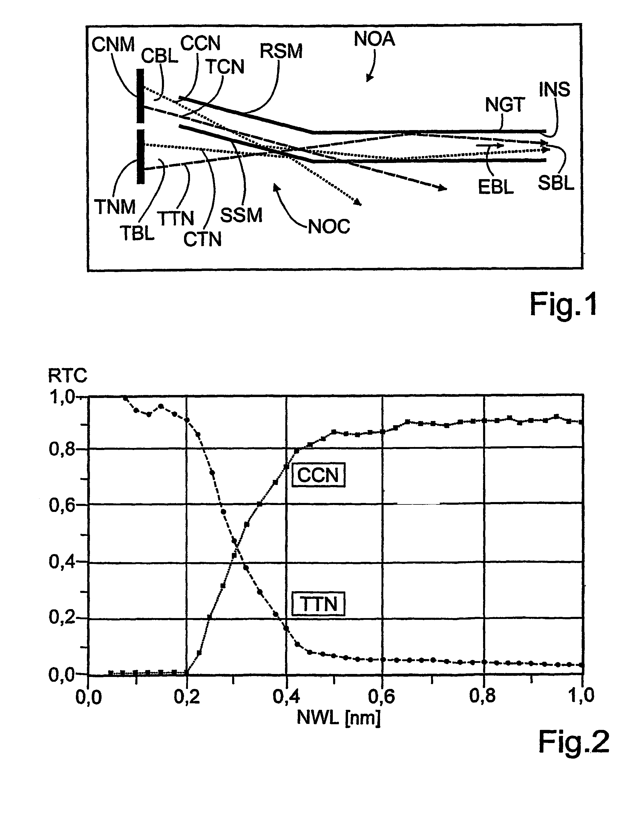
[0020]FIG. 1 depicts the neutron-optical component array NOA for the specific spectral shaping of neutron beams or pulses. In the selected embodiment a cold moderator CNM for neutrons is arranged closely adjacent a thermal moderator TNM for neutrons. Both moderators CNM, TNM measure 12×12 cm in cross-section and are separated by a gap of 0.5 cm. Instead of a representation of an angular arrangement between the two moderators CNM, TNM their radiation directions CBL, TBL are indicated as being angular relative to each other. The cold moderator CNM emits a neutron spectrum having a maximum of cold neutrons CCN and a smaller proportion of thermal neutrons CTN. On the other hand, the thermal moderator TNM generates a maximum of thermal neutrons TTN and a lesser proportion of cold neutrons CTN. The thermal moderator TNM is arranged directly opposite a neutron guide NGT which conducts the coupled-in neutrons to a place of experiment not shown in FIG. 1. The neutron guide NGT has a cross-se...


PUM


Abstract

A neutron-optical component array in which the beam paths of the individual moderators are combined in a concerted manner so as to create a superimposed neutron beam with an effective mean beam direction. The superimposed neutron beam has a multi spectrum composed of the single spectrums of several moderators, whereby a larger spectral width is obtained, making various applications in different neutron energy fields possible. The multi spectrum can be further improved in terms of the intensity thereof and the beam quality by adding further neutron-optical components, particularly in the form of an energy-depending switching super reflector, and by switching between moderators.

Description

BACKGROUND OF THE INVENTION[0001]1. Field of the Invention[0002]The invention relates to a neutron-optical component array for the specific spectral shaping of neutron beams or pulses in a neutron guide or beam hole between a fast neutron source with several moderators of different structures arranged closely adjacent each other for generating slow neutrons of different energy spectra as well as for their radiation in predetermined radiation directions and to at least one place of experiment.[0003]2. The Prior Art[0004]Neutron beams serve in a broad spectrum of scientific examinations ranging from pure basic science to application-related examinations in the field of research of the structure of matter. Here, neutrons function quasi as sensors which penetrate into the matter. Neutrons impinging upon atoms of structured matter are either scattered in a manner characteristic of the atoms or they are absorbed by the atoms by emitting characteristic radiation. For most applications, as ...

Claims


Application Information

Patent Timeline
Patent Type & Authority Patents(United States)
IPC IPC(8): G21K1/06G21K1/00G21K3/00
CPCG21K1/06
Inventor MEZEI, FERENCRUSSINA, MARGARITA
Owner HAHN MEITNER INSTITUT FUR KERNFORSCHUNG BERLIN
Learn More