Method for operating a ground milling machine with height-adjustable milling roller

a milling machine and height-adjustable technology, which is applied in the direction of slitting machines, constructions, roads, etc., can solve the problems of motor standstill, lowering of milling rollers, and damage to chisels on milling rollers

Active Publication Date: 2015-02-24
BOMAG
View PDF15 Cites 5 Cited by
  • Summary
  • Abstract
  • Description
  • Claims
  • Application Information

AI Technical Summary

Benefits of technology

[0005]It is an object of the present invention to provide measures for avoiding or reducing the problems occurring in the prior art.
[0008]A tumbling movement means that the milling roller is not lowered in a rigidly straight or rigidly horizontal manner, but that the downward movement is superimposed with a swaying movement of the milling roller axis, thus producing a swaying or staggering lowering movement. In comparison with a rigidly straight lowering of the milling roller, the increase of the braking torque acting on the milling roller will be lower during the lowering with a superimposed tumbling movement. Moreover, the chisels and chisel holders will be protected. Preferably the tumbling movement is guided in such a way that at most only 50% of the milling cutters on an engagement line are in engagement with the ground material. As a result, a more rapid penetration of the milling rotor into the ground material, especially hard ground material, is achieved.
[0012]The method in accordance with the present invention offers many advantages. The method in accordance with the present invention ensures that there are fewer malfunctions in milling operation, for example, thereby increasing operating convenience and improving operational reliability of the ground milling machine. Furthermore, the chisels and the chisel holders on the milling roller are protected, which consequently extends service life.
[0016]Alternatively or, if necessary, in addition to a control of the lowering speed, during the lowering of the milling roller the momentary speed or power of the drive motor of the ground milling roller will be detected and the lowering speed of the milling roller will automatically be controlled and changed depending on said detected speed or power in a closed-loop control process by way of a control loop. This advantageously provides for the maximum possible lowering speed of the milling roller at any time during operation.
[0018]If the construction machine comprises several height-adjustable milling rollers, the lowering can separately or jointly be controlled via open-loop and / or closed-loop control. If several actuators are provided for the height adjustment of a milling roller, the lowering speed can preferably be controlled via open-loop and / or closed-loop control for every single actuator (in a separate or in a common control loop). Despite the tumbling movement, open-loop and / or closed-loop control of the lowering speed of the milling roller is therefore possible. It is also possible to realize a tumbling movement of the milling roller by a separate triggering of the actuators and the respective open-loop and / or closed-loop control of the lowering speeds. The open-loop and / or closed-loop control of the lowering speed can be produced, for example, by a separate adjustment of the hydraulic pressure in the actuators and / or the volume flow (of a hydraulic oil or the like) to the respective actuators.
[0021]In order to prevent the killing of the drive motor, it is also possible to control and thus change the momentary travelling speed of the ground milling machine depending on the momentary lowering speed of the milling roller by way of closed loop and / or open loop control. This can occur as an alternative and / or in addition to other closed-loop and / or open-loop control processes. The idea is finding an operating point during the lowering of the milling roller for the ground milling machine at which the power provided by the drive motor is distributed among the individual consumers (travelling drive, rotational drive, actuators) in the best possible way without loading the drive motor beyond its optimal maximum power point.

Problems solved by technology

The lowering of the milling roller is problematic during the operation of a ground milling machine with a height-adjustable milling roller in order to allow the milling roller to penetrate the ground material (e.g., an asphalt bed) or in order to increase the milling depth of the milling roller which is already in engagement with the ground material.
During abrupt or rapid lowering of the milling roller, the drive motor of the ground milling machine can be subjected to loads that exceed its power limit, leading to standstill of the motor or—even worse—to damage thereof.
Moreover, the chisels on the milling roller can be damaged.

Method used


Image

  • Method for operating a ground milling machine with height-adjustable milling roller
  • Method for operating a ground milling machine with height-adjustable milling roller
  • Method for operating a ground milling machine with height-adjustable milling roller

Examples


Embodiment Construction

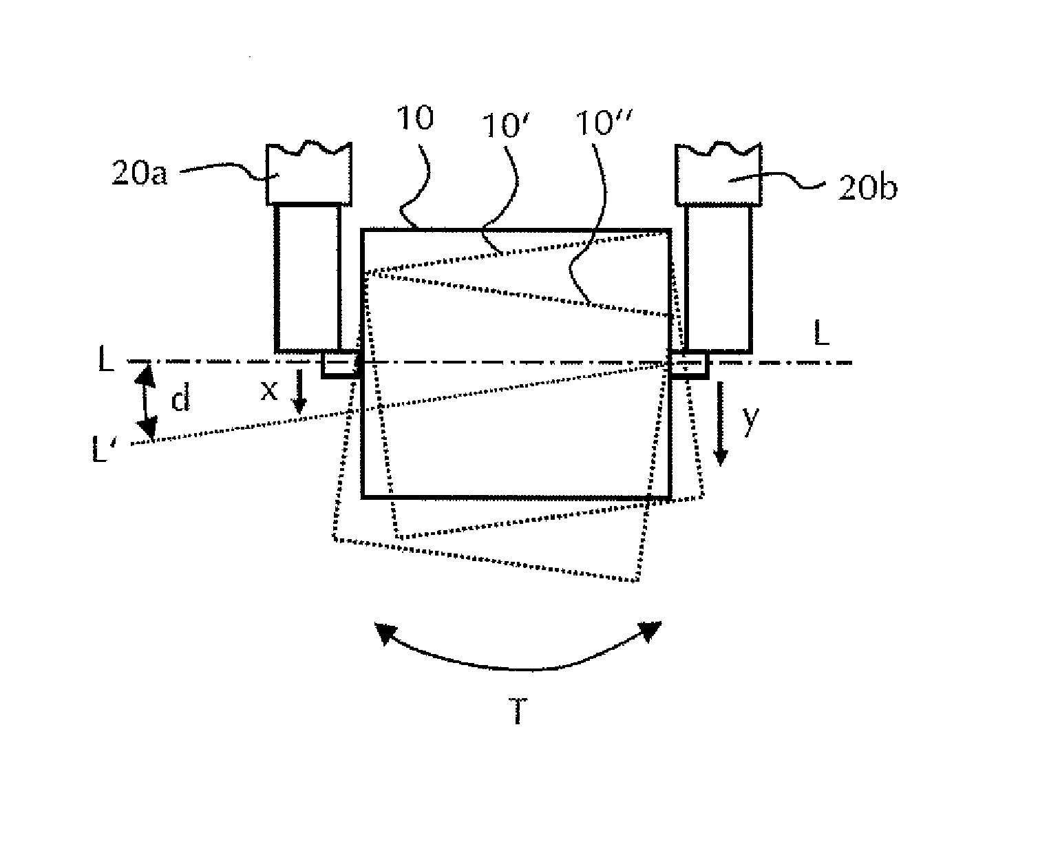
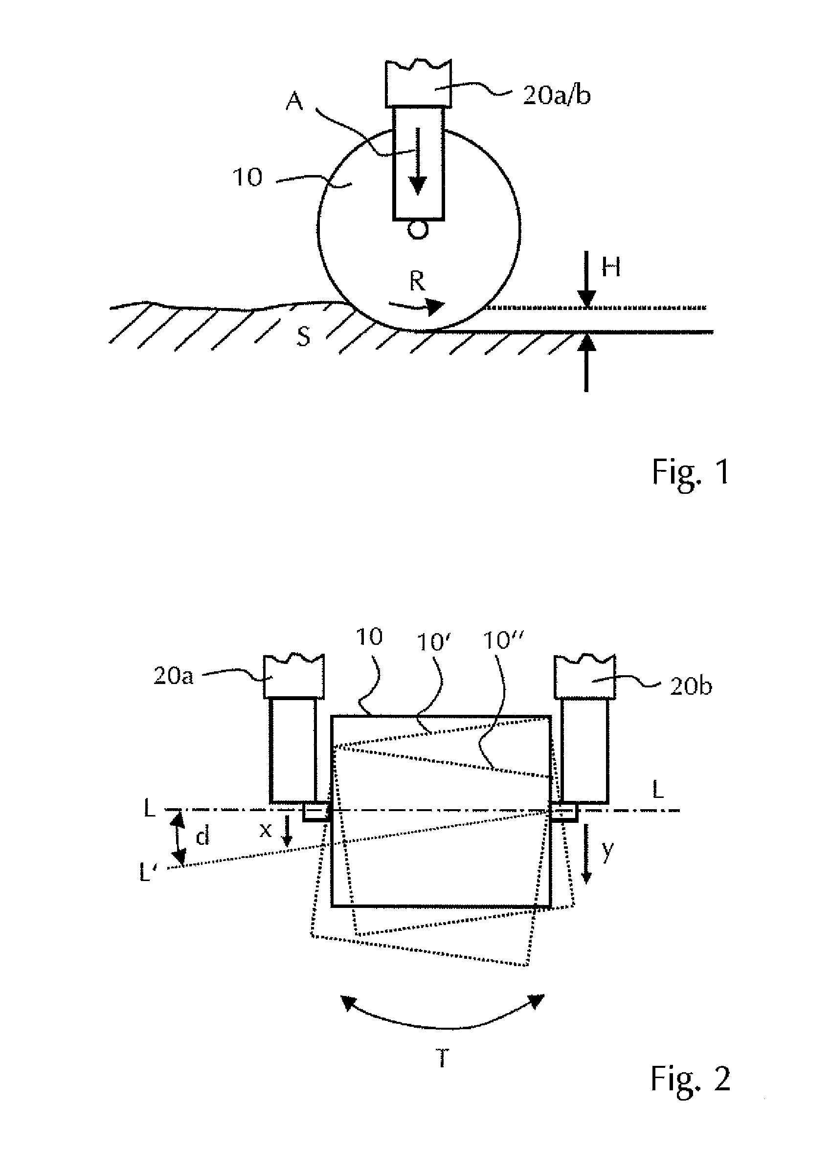
[0027]FIG. 1 shows a milling roller 10 in a schematic side view. The milling roller 10 is arranged in a height-adjustable manner via two actuators 20a / 20b on a ground milling machine (not shown in closer detail). The actuators 20a / 20b are disposed at the axial ends of the milling roller 10, as shown in the front view of FIG. 2. Several chisels (not shown in closer detail) are arranged on the milling roller 10, which chisels loosen and remove ground material S with a defined height H (milling depth) in the stated direction of rotation R (optionally also in the opposite direction of rotation) during rotation of the milling roller 10.

[0028]The milling depth H can be changed in milling operation via a height adjustment by means of the actuators 20a / 20b, which especially can be hydraulically actuated actuators (so-called lifting columns). Furthermore, the rotating milling roller 10 can be lowered into the ground material S via the actuators 20a / 20b at the beginning of the milling operati...


PUM


Abstract

The present invention relates to a method for operating a ground milling machine which comprises at least one height-adjustable milling roller, wherein the milling roller performs a tumbling movement (T′) which is controlled by way of open-loop and / or closed-loop control during lowering in operation. The present invention further relates to a control device for the closed-loop and / or open-loop control of this method, and also to a ground milling machine with such a control device.

Description

CROSS-REFERENCE TO RELATED APPLICATIONS[0001]The present application is a submission under 35 U.S.C. §371 of International Application No. PCT / EP2011 / 001938, filed Apr. 15, 2011, which claims priority to German Application No. 10 2010 015 173.4, filed Apr. 16, 2010, the disclosures of which are hereby expressly incorporated by reference herein in their entireties.FIELD OF THE INVENTION[0002]The present invention relates to a method for operating a ground milling machine which comprises at least one height-adjustable milling roller. The present invention further relates to a control device for performing this method, and also to a ground milling machine.BACKGROUND OF THE INVENTION[0003]Ground milling machines with height-adjustable milling rollers or milling rotors are known from the prior art, with the milling depth in the ground material (of a road surface cover) to be processed being changed via the height adjustment or being adjusted as required by a specific situation, e.g., wit...

Claims


Application Information

Patent Timeline
Patent Type & Authority Patents(United States)
IPC IPC(8): E01C23/088E01C23/12E02F9/20
CPCE01C23/088E01C23/127E02F9/2025
Inventor WACHSMANN, STEFFEN
Owner BOMAG
Why Eureka
Try Eureka