
Roofing system, roof panel therefor, and method of assembling a roof

Inactive Publication Date: 2005-12-29
SMARTROOF
View PDF13 Cites 6 Cited by
  • Summary
  • Abstract
  • Description
  • Claims
  • Application Information

AI Technical Summary

Benefits of technology

[0014] It is an object of the present invention to provide a roofing system, and roof panels therefor, which avoids or reduces the above-stated problems with the Unilin type of construction technique. The present invention utilises roof panels which are configured to lie across the roof as in the TRADA disclosure, and seeks to avoid or reduce the practical problems which lie in the way of a skilled person seeking to put the teaching of that document into effect.
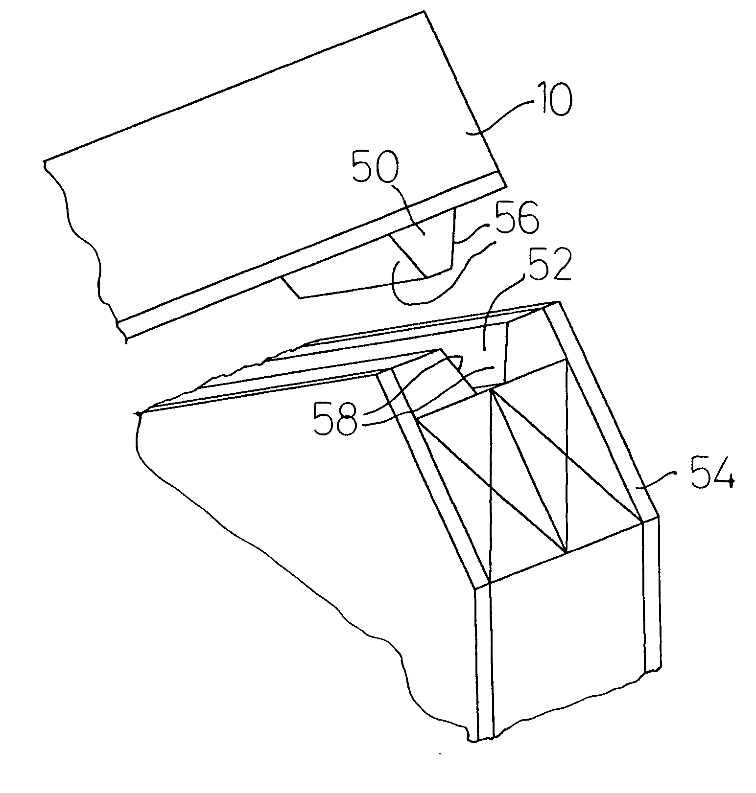
[0016] The provision of a tongue and groove connection between the gable means and the ends of the panels ensures a positive location for the panels (facilitating ease of construction) and helps to maintain the separation of the gable means in the assembled structure.
[0019] Preferably, the tongue and groove have inclined sides and a flat bottom. The flat bottom provides a bearing surface supporting at least part of the weight of the panel in use. The inclined sides facilitate ease of fitment, i.e. the width of the bottom wall of the tongue is less than the width of the open end of the groove so that precise location of the panel above the gable means is not required to ensure cooperation of the tongue and groove.

Problems solved by technology

It is a recognised disadvantage of such truss designs that the intermediate members cause obstructions within the loft space, and render the loft space substantially unusable as living accommodation.
However, attic trusses are heavier than traditional trusses and are difficult to handle on site.
Another significant factor for house builders is the cost of materials and labour used in building domestic dwellings, particularly low-cost domestic dwellings.
Whilst the attic trusses allow a home with a given number of bedrooms to be constructed on a smaller ground area, and therefore at greater density, the materials and labour costs of construction are high.
It is a recognised disadvantage of this type of construction that the intermediate purlins lie within the loft space.
Because of the considerable weight of the roof panels, and the snow load they must be designed to withstand, the purlins are necessarily of large cross-section, and so present a significant obstruction within the loft space.
Furthermore, because the purlins must span the width of the building they are necessarily heavy and difficult to transport and handle on site (whether of wood, steel or composite material).
It is another recognised disadvantage that the weight of the panels is at least partly supported on the front and back walls, and tends to push those walls apart.
However, the TRADA document is an incomplete disclosure and only sets out the principles of the construction techniques, and not the practical details thereof; accordingly, the TRADA document alone does not provide a disclosure which would enable a skilled person to construct a roof.
In addition, the distance which each panel must be able to span between the gable ends is limited by the strength of the panels, and it is desired that the maximum span be around 5.5 metres; such a span is suitable for the vast majority of low-cost domestic housing applications.

Method used


Image

  • Roofing system, roof panel therefor, and method of assembling a roof
  • Roofing system, roof panel therefor, and method of assembling a roof
  • Roofing system, roof panel therefor, and method of assembling a roof

Examples


Embodiment Construction

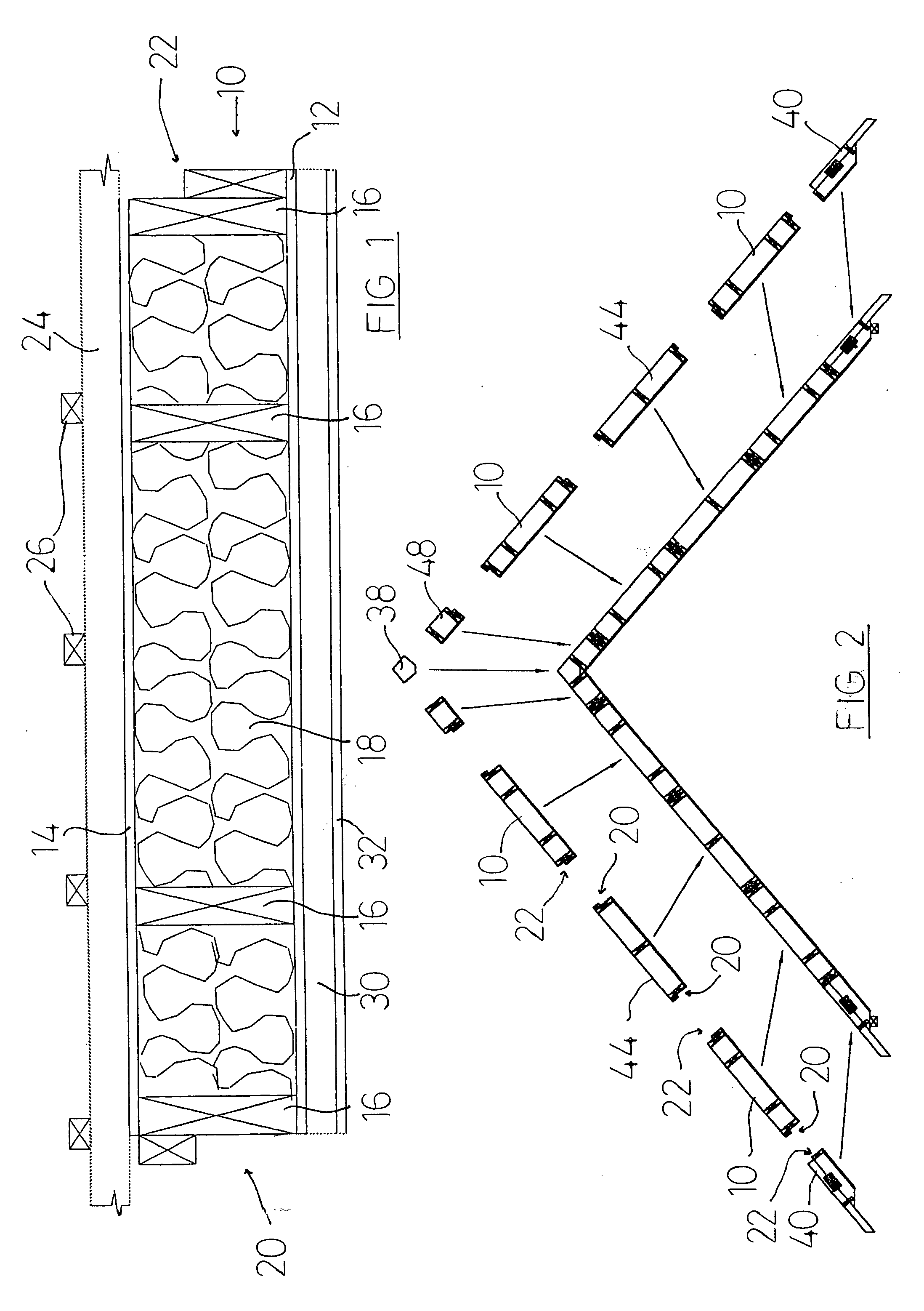
[0037]FIG. 1 shows a cross-sectional view of a roof panel 10. The panel comprises a first sheet 12 (which is the innermost sheet in use), and a second sheet 14 (which is the outermost sheet in use), which are interconnected by four longitudinal beams 16. Insulating material 18 fills the volume between the sheets 12 and 14 which is not occupied by the beams 16.

[0038] It is desirable but not essential that the panels be made from renewable and recyclable materials, and natural materials such as wood are preferred. In this (preferred) embodiment the beams 16 are of wood, the sheet 12 is of plywood, and the sheet 14 is of fibreboard. The beams 16 in this embodiment have cross-sectional dimensions of approximately 50 mm by 197 mm, and the sheets 12, 14 are approximately 12 mm thick.

[0039] To ensure the required weatherproofing, the outermost sheet 14 includes a weatherproof material, and preferably a “breathable” material; in this embodiment, therefore, the sheet 14 comprises a sheet o...


PUM


Abstract

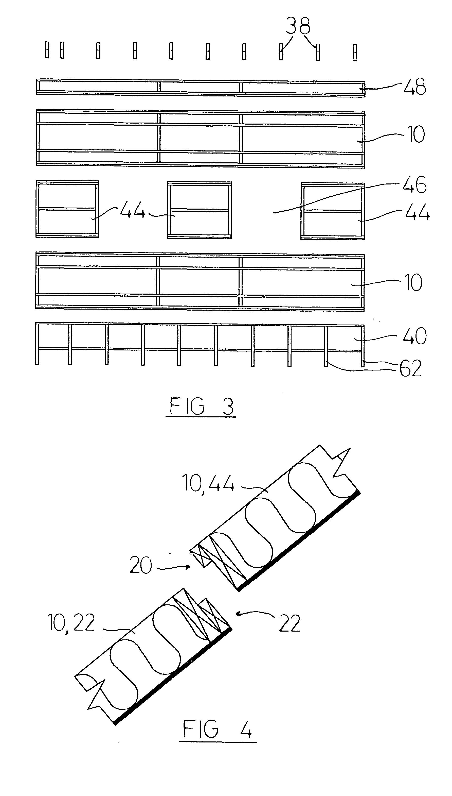
This invention relates to a roofing system, to a roof panel therefor, and to a method of assembling a roof. According to the invention, there is provided a roofing system for a building, the building having four walls, an opposed two of the walls including gable means, the roofing system comprising a number of roof panels which can span the distance between the gable means and be supported thereby and a number of intermediate panels which cannot span the distance between the gable means, the roof panels and the intermediate panels having cooperating surfaces whereby the intermediate panels can be supported by the roof panels. The use of intermediate panels allows the installation of windows into the roof.

Description

FIELD OF THE INVENTION [0001] This invention relates to a roofing system, to a roof panel therefor, and to a method of assembling a roof. The invention is expected to find its greatest utility in relation to roofs for domestic dwellings, and the following description therefore relates to such use. It may, however, be that the invention also has utility in relation to commercial or industrial buildings and such applications are not excluded. DESCRIPTION OF THE PRIOR ART [0002] Domestic dwellings can have flat roofs or pitched roofs; the invention relates to the latter. A pitched roof is traditionally created by a number of roof trusses comprising wooden frames (typically pre-fabricated) which are set upon the brick or timber-frame walls of the building. A layer of waterproofing material is laid over the trusses and battens are mounted thereupon which support the tiles or other outermost roof covering. [0003] The trusses are usually of general triangular shape, with a horizontal (in u...

Claims


Application Information

Patent Timeline
IPC IPC(8): E04B2/08E04B2/32E04B2/46E04B7/04E04B7/22E04D3/36E04G21/26
CPCE04G21/26E04B7/225
Inventor BOUVERAT, RICHARD
Owner SMARTROOF
Learn More