Out-of-plane-accelerometer

Active Publication Date: 2018-06-14
COLIBRYS
View PDF10 Cites 4 Cited by
  • Summary
  • Abstract
  • Description
  • Claims
  • Application Information

AI Technical Summary

Benefits of technology

[0031]In one embodiment, the wafer etching in particular of the second wafer layer is done by plasma etching, preferably by Deep reactive-ion etching (DRIE). Compared to anisotropic wet etching as for instance potassium hydroxide (KOH), this allows to realize vertical sidewalls in a wafer layer and thus to realize smaller openings in the wafer layer. Therefore, the surface of the seismic mass can be maximised compared to the cut-out necessary for the spring system, the pillar and/or the mass frame. Thus, the same capacitive values can be achieved with smaller accelerometers which are stiffer and thus less sensible to bias and bias instability. This technology becomes in particular advantageous for thicker wafer layers for which the old technology like KOH implies larger openings between two parts of the same wafer layer. Since the openings in the fi

Problems solved by technology

They have the disadvantage to be more complex in production, because the accelerometer is composed of a triple stack of wafer layers.
Any bias acceleration error will be accumulated over time with a square time dependency.
However, such an approach is limited by the stability of the bias over time and temperature.
Therefore, even the known out-of-plane accelerometers are not good enough for certain applications.
However, this decoupling structure cannot prevent any bias created in the sensor box itself due to temperature changes or ageing effe

Method used


Image

  • Out-of-plane-accelerometer
  • Out-of-plane-accelerometer
  • Out-of-plane-accelerometer

Examples


Embodiment Construction

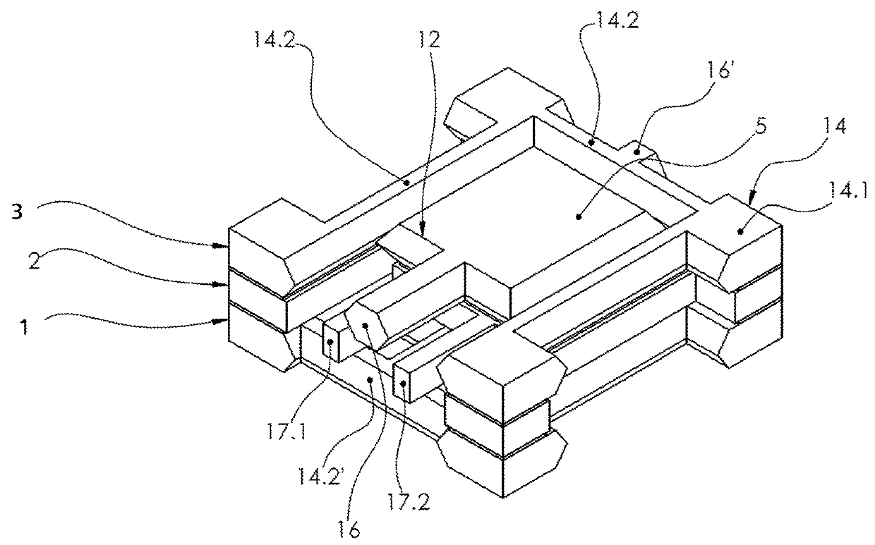
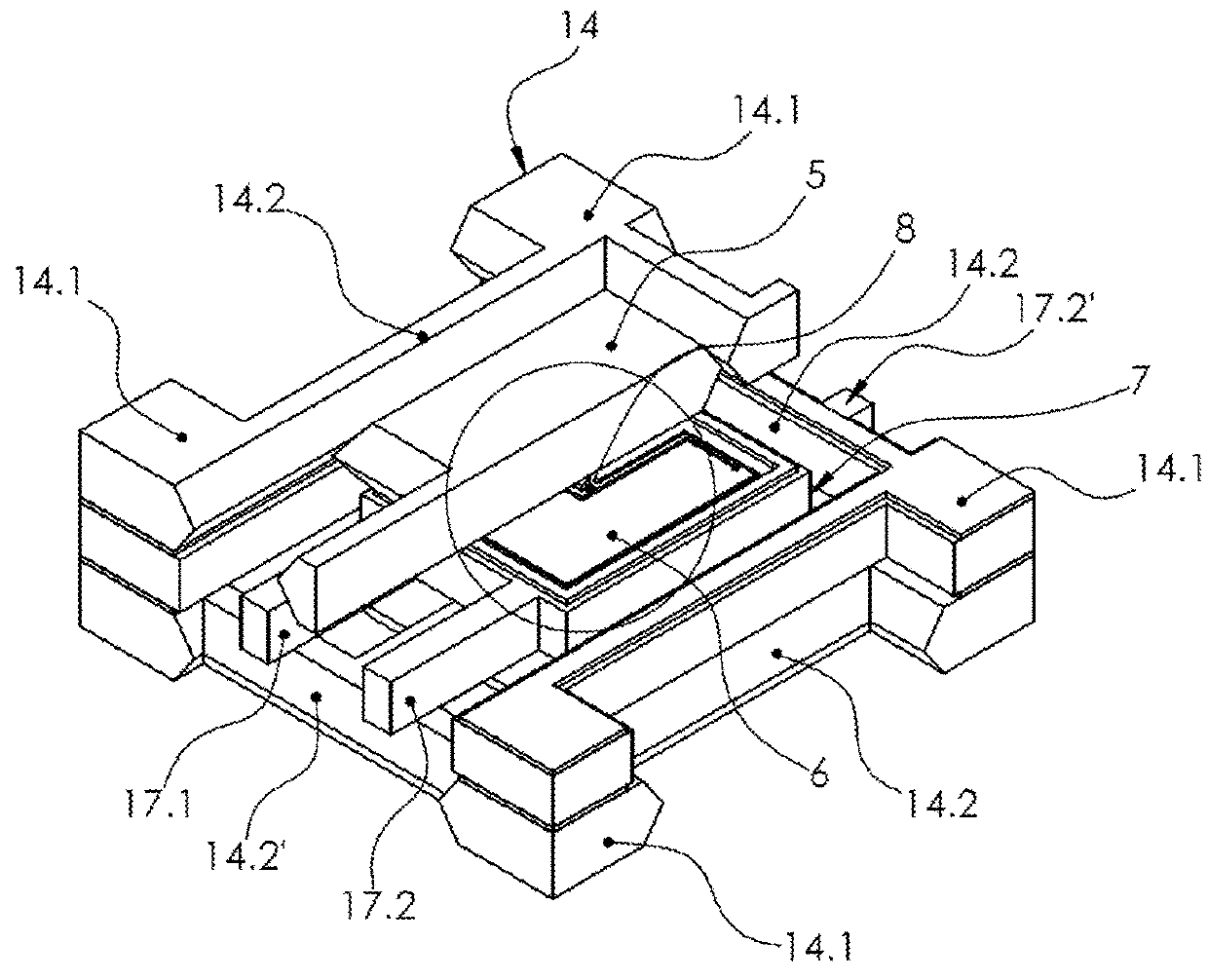
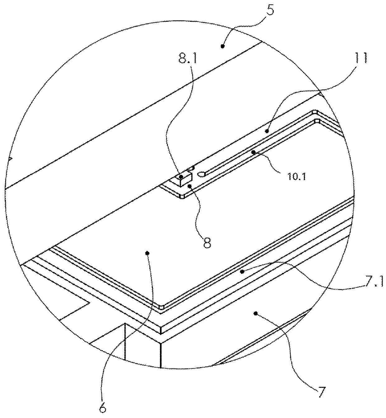
[0042]FIGS. 1 to 4 show different views of an exemplary embodiment of an accelerometer.

[0043]The accelerometer comprises a sensor box 12 and a decoupling structure 14.

[0044]The accelerometer is formed of parts arranged in three different parallel planes. The parts of the accelerometer arranged in the first plane are formed preferably out of a first wafer layer 1. The parts of the accelerometer arranged in the second plane are formed preferably out of a second wafer layer 2. The parts of the accelerometer arranged in the third plane are formed preferably out of a third wafer layer 3.

[0045]The sensor box 12 comprises a first capacitor plate 4 in the first plane, a second capacitor plate 5 in the third plane, a seismic mass 6 and a mass frame 7 in the second plane.

[0046]The mass frame 7 is arranged between the first capacitor plate 4 and the second capacitor plate 5 and connected to the first capacitor plate 4 and the second capacitor plate 5 in a fixed positional relationship (rigid l...


PUM


Abstract

Accelerometer including a seismic mass in a plane and a first capacitor plate and a second capacitor plate arranged parallel to the plane. The seismic mass is arranged in between the first capacitor plate and the second capacitor plate. The first capacitor plate and the second capacitor plate are configured to detect movements of the seismic mass out of the plane. A pillar extending from the first capacitor plate to the second capacitor plate through a cut-out in the seismic mass for stiffening the accelerometer.

Description

FIELD OF THE INVENTION[0001]The present invention concerns accelerometers, in particular out-of-plane accelerometers, and a method to manufacture them.DESCRIPTION OF RELATED ART[0002]Most accelerometers today are microelectromechanical systems (MEMS) devices. Such accelerometers have a seismic mass which will exhibit a displacement proportional to the acceleration. The mass displacement is sensed through capacitive detection. There are two types of accelerometers. In-plane accelerometers detect movements in the plane of the seismic mass, i.e. the capacitive system and the seismic mass are arranged in the same plane. This is for example realized by comb fingers on the mobile seismic mass relative to fixed comb fingers on the counter-electrode forming the capacitor. They have the advantage of cheap manufacturing and are used in most consumer electronics. Out-of-plane accelerometers detect accelerations by movements out of the plane of the seismic mass. Therefore, two capacitor plates ...

Claims


Application Information

Patent Timeline
IPC IPC(8): G01P15/125B81B7/02G01P15/18B81B3/00G01P15/08G01P1/02B81B7/00
CPCG01P15/125B81B7/02G01P15/18B81B3/0062G01P15/0802G01P1/023B81B7/0048B81B2201/0235G01P2015/0814G01P2015/0828
Inventor ZWAHLEN, PASCALBIRLING, SOPHIEDUTOIT, BERTRAND
Owner COLIBRYS
Why Eureka
Try Eureka