Method of reducing steering instability in hydraulic power steering systems

a technology of hydraulic power steering and steering instability, which is applied in the direction of steering initiation, instruments, vessel construction, etc., can solve the problems of steering instability, steering instability, and vehicles with steering instability may exhibit excessive noise and/or vibration, so as to reduce steering instability, less steering instability, and less steering instability

Inactive Publication Date: 2010-03-04
STEERING SOLUTIONS IP HLDG +1
View PDF6 Cites 0 Cited by
  • Summary
  • Abstract
  • Description
  • Claims
  • Application Information

AI Technical Summary

Benefits of technology

[0010]The present invention provides a method for reducing steering instability in a hydraulic power steering system for a vehicle having a pair of cylinder lines through which hydraulic fluid is conveyed in assisting turning a vehicle wheel, including the steps of determining which of said pair of cylinder lines results in less steering instability when the vehicle wheel is turned; calculating the fluid inertance of the hydraulic fluid conveyed through the cylinder line that results in less steering instability; and altering at least one dimension of the cylinder line that results in greater steering instability when the vehicle wheel is turned to substantially match the fluid inertance thereof to the calculated fluid inertance.

Problems solved by technology

Instability in hydraulic power steering systems (“steering instability”) is a common problem that can develop when integrating a hydraulic power steering system into the architecture of a vehicle.
During a steering event, vehicles having steering instability may exhibit excessive noise and / or vibration when the steering system goes unstable.
Steering instability is the result of undamped eigenvalues, i.e., resonances, in the open loop control response of the vehicle steering system.
Steering instability typically manifests itself in either a left or a right turn.
Less frequently, steering instability occurs during turns in both directions.
Either way, steering instability will usually develop into a warranty issue or customer complaint if not resolved.
However, these attempts are typically vehicle specific and can have significant impact on other ride and handling attributes.
. . etc. . . . Typically, such vehicle changes are beyond the control of steering system suppliers, and require the involvement of the OEM customer and / or chassis component or system suppliers.
However, such tuning can adversely affect other steering system attributes.
Tuning a supply line to reduce steering instability typically conflicts with tuning intended to address other steering system-related objectives like reducing pump noise or improving steering feel, whereas tuning a return line to reduce steering instability typically results in system packaging and / or cooling issues because the amount of steel required in the return line to adequately dissipate heat usually conflicts with the amount required to substantially reduce steering instability.

Method used


Image

  • Method of reducing steering instability in hydraulic power steering systems
  • Method of reducing steering instability in hydraulic power steering systems
  • Method of reducing steering instability in hydraulic power steering systems

Examples


first embodiment

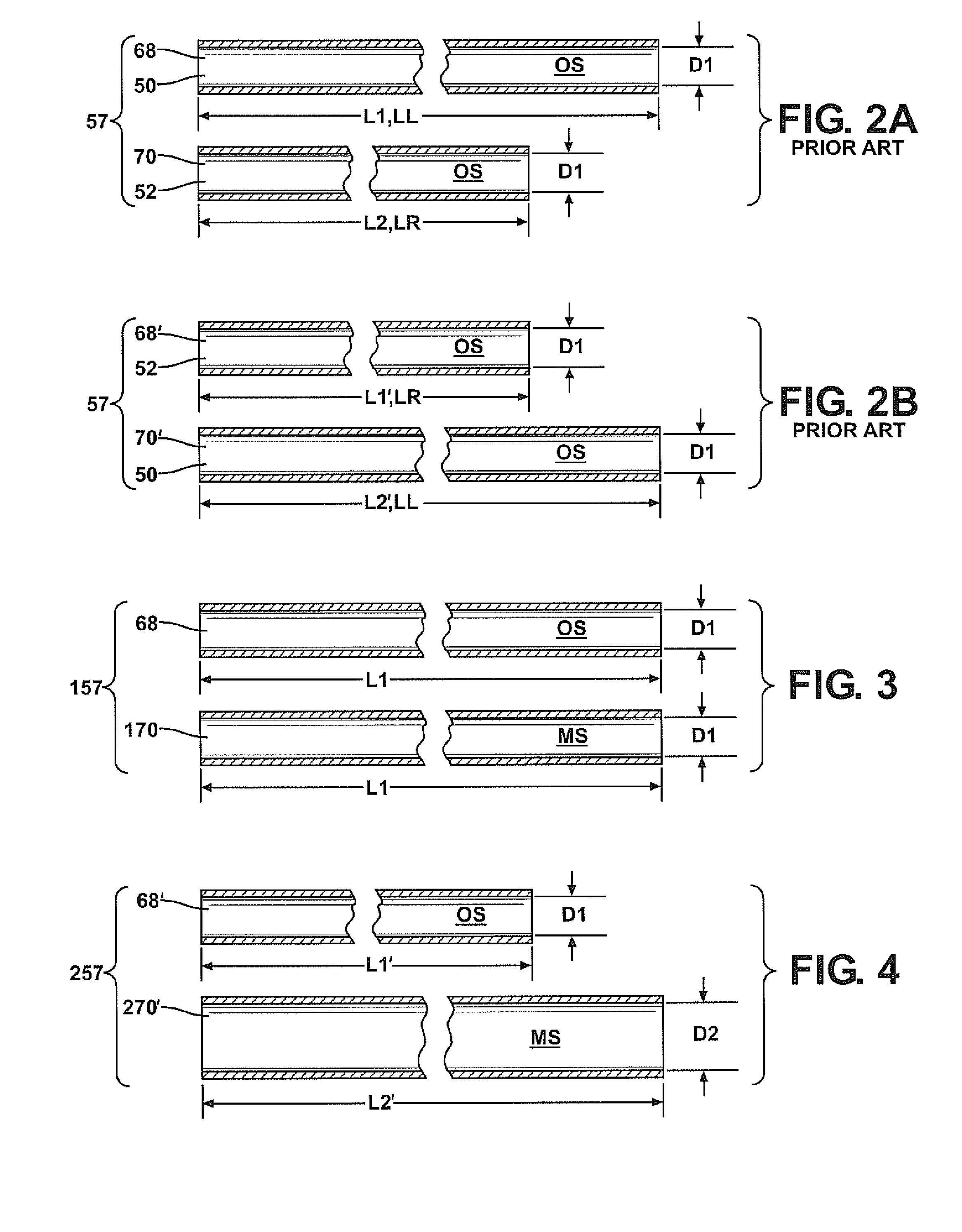
[0038]With reference to FIG. 2A, in the case where the steering instability is found in the steering direction associated with the shorter, right hand cylinder line 52, 70, second line length L2 of the second or right hand cylinder line 52, 70 is extended to match length L1 (which may be overall length LL) of the first or left hand cylinder line 50, 68, their common first flow areas or inner diameters D1 remaining unaltered from their original states, as shown in FIG. 3, wherein the resulting first embodiment altered pair of cylinder lines 157 includes modified second cylinder line 170 which produces substantially the same fluid inertance as that of its paired first cylinder line 68.

[0039]With reference to FIG. 2B, however, in the case where second cylinder line 70′ is longer, left hand cylinder line 50, it may not be possible to reduce its overall, second line length L2′, LL to match shorter overall length L1′, LR of first, right hand cylinder line 52, 68′. Therefore, application o...

second embodiment

[0040]Increasing the cross-sectional flow area will decrease the fluid inertance of a given line, and decreasing its cross-sectional flow area will increase its fluid inertance. As shown in FIG. 2B, the respective lengths L1′ and L2′ of first and second cylinder lines 68′ and 70′ are different, but through application of the inventive method the fluid inertances of cylinder lines 68′, 70′ are made substantially equivalent by increasing the inner diameter of longer second line 70′ from original, first flow area or first diameter D1 to larger, second flow area or second diameter D2 to yield modified second cylinder line 270′ of FIG. 4, which depicts second embodiment altered pair of cylinder lines 257 resulting from application of the inventive method.

[0041]Should the “stable” first cylinder line 68 be the longer, and the “unstable” second cylinder line 70 be the shorter of the pair of cylinder lines, as illustrated in FIG. 2A, and it not be possible or desirable to lengthen second cy...

fourth embodiment

[0042]A changed flow area of the second cylinder line 70, 70′ need not be constant or over its entire length in order to substantially match its fluid inertance to that of first cylinder line 68, 68′. Referring to FIG. 6, there is shown fourth embodiment altered pair of cylinder lines 457 resulting from the inventive method applied to a pair of lines wherein first line 68 is the longer of the two, and modified second line 470 is the shorter, i.e., their original states may be as lines 68, 70 illustrated in FIG. 2A. In FIG. 6, the second line length L2 of modified second cylinder line 470 includes a modified middle segment or portion LA disposed between opposite end segments or portions LB and LC. The overall length L2 of modified second line 470 shown in FIG. 6 may be substantially unchanged from that of original state second line 70 shown in FIG. 2A. In modified second line 470, the flow area or inner diameter of middle portion LA has been reduced from original first flow area or d...


PUM


Abstract

A method for reducing steering instability in a hydraulic power steering system for a vehicle having a pair of cylinder lines through which hydraulic fluid is conveyed in assisting turning a vehicle wheel, including the steps of determining which of said pair of cylinder lines results in less steering instability when the vehicle wheel is turned; calculating the fluid inertance of the hydraulic fluid conveyed through the cylinder line that results in less steering instability; and altering at least one dimension of the cylinder line that results in greater steering instability when the vehicle wheel is turned to substantially match the fluid inertance thereof to the calculated fluid inertance.

Description

CROSS-REFERENCE TO RELATED APPLICATION[0001]This application claims priority to and all benefit of U.S. Provisional Patent Application Ser. No. 61 / 093,774 filed Sep. 3, 2008, the complete disclosure of which is expressly incorporated herein by reference.BACKGROUND OF THE INVENTION[0002]1. Field of the Invention[0003]The subject invention relates generally to methods for reducing steering instability in hydraulic power steering systems.[0004]2. Description of the Related Art[0005]Instability in hydraulic power steering systems (“steering instability”) is a common problem that can develop when integrating a hydraulic power steering system into the architecture of a vehicle. During a steering event, vehicles having steering instability may exhibit excessive noise and / or vibration when the steering system goes unstable. Steering instability is the result of undamped eigenvalues, i.e., resonances, in the open loop control response of the vehicle steering system. Steering instability typi...

Claims


Application Information

Patent Timeline
Patent Type & Authority Applications(United States)
IPC IPC(8): G06F19/00
CPCB62D5/062
Inventor BEYERLEIN, ROBERT E.
Owner STEERING SOLUTIONS IP HLDG
Why Eureka
Try Eureka