Device and method for milling of materials

a technology of a milling device and a material, which is applied in the direction of shaping cutters, manufacturing tools, percussive tools, etc., can solve the problems of not always being able to change the spindle speed, not always being able to carry out a stable milling operation, and poor and irregular finish of the surface of the milled material, etc., to achieve even more efficient milling, improve the effect of milling, and flexibility in the tuning of the natural frequency

Active Publication Date: 2010-11-25
SANDVIK INTELLECTUAL PROPERTY AB
View PDF49 Cites 8 Cited by
  • Summary
  • Abstract
  • Description
  • Claims
  • Application Information

AI Technical Summary

Benefits of technology

[0027]According to an advantageous embodiment of the device, the recess is adapted to receive two or a plurality of mass elements, and each mass element is axially tunable and axially lockable by means of said tuning members and lock members. In this way, flexibility is obtained as for the tuning of the natural frequencies of the device and different masses can easily be obtained in order to optimize the natural frequency of the milling operation in question, by means of which the milling becomes further improved and still more efficient.
[0028]According to an additional advantageous embodiment of the device, the respective mass element is replaceably arranged in the recess. This contributes further to flexibility regarding the tuning of the natural frequencies of the device, since a mass element can be replaced by a mass element of higher or lower weight, a mass element of stiffer or less stiff material, or a mass element having greater or smaller axial extension, and thus the milling becomes even more efficient.

Problems solved by technology

Elongate milling cutter bodies, in particular when mounting with a great protrusion length, have a tendency to cause a poor and irregular finish of the surface in the milled material, caused by so-called chatter, which may appear as waves on the milled surface of the workpiece.
For a specific spindle speed, including, for example, the number of revolutions per time unit of the spindle, there is a critical axial cutting depth and in case of cutting depths that are greater than the critical axial cutting depth, too great vibrations arise to be able to carry out a stable milling operation.
However, it is not always possible to change the spindle speed to avoid stability problems, which may at least be due to speed control limitations in the machine and / or because increased cutting speed may cause higher temperature in the cutting zone, which in turn results in faster tool wear.
However, the methods and apparatuses mentioned above do not provide sufficiently flexible and efficient solutions to efficiently overcome stability problems and vibration problems in milling.

Method used


Image

  • Device and method for milling of materials
  • Device and method for milling of materials
  • Device and method for milling of materials

Examples


first embodiment

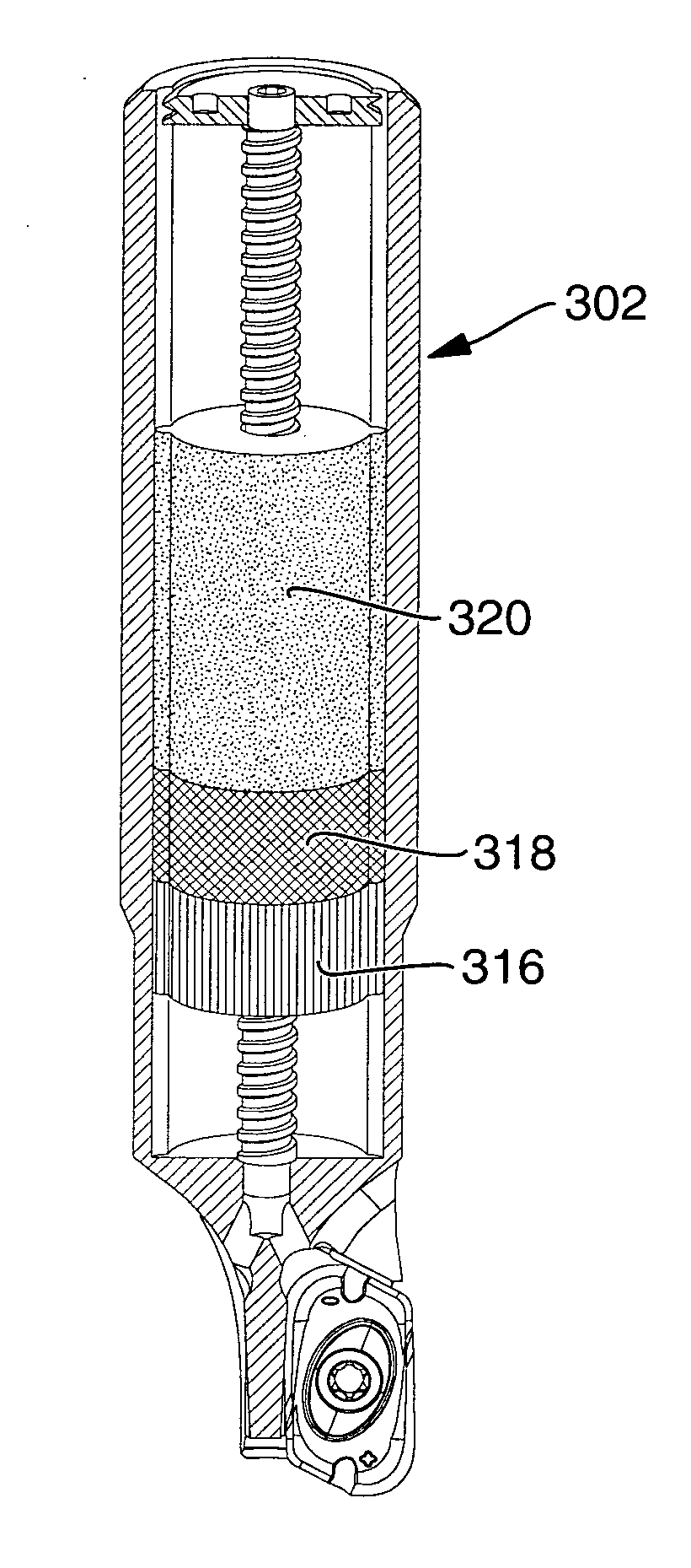
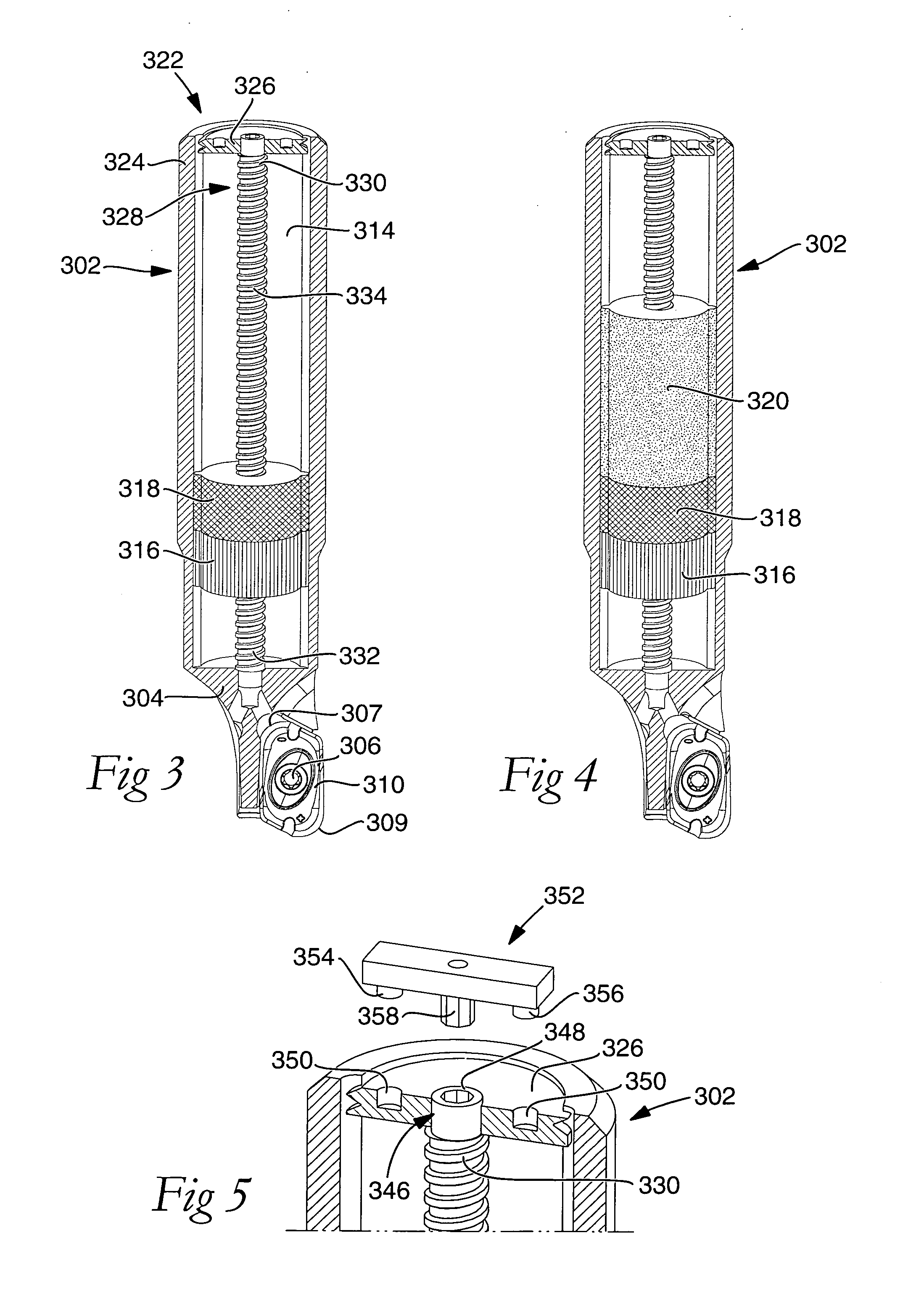
[0059]FIGS. 3-6 schematically show a milling tool for chip removing metal machining including an elongate milling cutter body 302 of the device, wherein the milling cutter body 302 at the second end portion 304 thereof is provided with mounting members 306 for mounting of an edged milling insert 310 peripherally on the milling cutter body 302 in a pocket. Here, the milling insert 310 is provided with two cutting edges 307, 309 and is accordingly indexable into two different active positions, but may be provided with one or more than two cutting edges. The mounting members 306 for a milling insert 310 have a conventional design and embrace in this case a fastening element 306 that is adapted to engage with a recess arranged in the milling insert 310 and is anchored in a fastening hole mouthing in the bottom surface of the pocket in the milling cutter body 302, for example, by threads. The milling cutter body 302 is provided with a central axial hole 314 that extends along the longitu...

third embodiment

[0065]FIG. 8 shows a milling cutter body 502 of the device, wherein the axial hole 504 of the milling cutter body 502 along essentially the entire axial extension thereof, from the first end portion 506 of the milling cutter body 502 to the second end portion 508 thereof, where the mounting members 510 of the milling cutter body for mounting of an edged milling insert 514 peripherally on the milling cutter body 502 are located, is provided with internal threads 518 constituting the first threaded members 518. The second threaded members 520, which together with the first threaded members 518 form tuning members and locking members, are arranged peripherally on the mass element 522 in the form of external threads. The mass element 522 is provided with an indentation 524 having, for instance, a hexagonal internal cross-section, or another non-circular cross-section, with which a tool is adapted to engage so as to, by rotation of the mass element 522, tune the axial position thereof, a...

fourth embodiment

[0066]FIG. 9 shows a milling cutter body 602 of the device, wherein the milling cutter body 602 at the first end portion 604 thereof is mountable in a rotatable spindle and is, at the second end portion 606 thereof, provided with mounting members 608 for mounting of an edged milling insert 612 peripherally on the milling cutter body 602. In an axial hole 616 arranged in the milling cutter body 602, the mass element is 618 arranged and has also here a smooth envelope surface and has a radial extension corresponding to the internal cross-section of the axial hole 616, whereby the mass element 618 is radially locked so that its radial motion in relation to the milling cutter body 602 is prevented. The tuning members of this embodiment include driving members in the form of a helical compression spring 620 arranged between the mass element 618 and the second end portion 606 and adapted to drive the mass element 618 toward the first end portion 604. The tuning members include in addition...


PUM

PropertyMeasurementUnit
massaaaaaaaaaa
natural frequencyaaaaaaaaaa
lengthaaaaaaaaaa

Abstract

Device and method for milling of materials including a milling cutter body including a first end portion and an opposite second end portion. The first end portion is connected to a rotatable spindle and the second end portion is provided with at least one cutting edge. The milling cutter body defines a longitudinal axis and is provided with an axial recess, wherein at least one mass element is arranged in the recess. The axial position of the mass element in relation to the milling cutter body is tuned by use of tuning members included in the device for the tuning of the natural frequency of the device. The mass element is axially locked in relation to the milling cutter body by use of lock members included in the device, in order to optimize the natural frequency of the device for the milling operation in question.

Description

CROSS-REFERENCE TO PRIOR APPLICATION[0001]This application claims priority to Swedish Application No. 0950366-5 filed May 25, 2009, which is incorporated by reference herein.TECHNICAL FIELD[0002]The present disclosure relates to a method and a device for milling of materials, for instance, titanium, aluminium, casting or another material. The device includes a milling cutter body including a first end portion and an opposite second end portion. The first end portion is connectable to a rotatable spindle or holder and the second end portion is provided with at least one cutting edge or mounting member for mounting at least one milling insert having at least one cutting edge. The milling cutter body defines a longitudinal axis, which extends through the first and second end portion, and is provided with an axial recess and at least one mass element arranged in the recess.BACKGROUND ART[0003]In milling, the performance of the milling is largely determined by the combined natural freque...

Claims


Application Information

Patent Timeline
Patent Type & Authority Applications(United States)
IPC IPC(8): B23C9/00B23C5/16
CPCB23C5/003B23C5/109B23Q11/0039Y10T407/22Y10T409/303752Y10T409/304312B25D2222/06B23C2226/27Y10T409/304032Y10T408/76B23B29/00B23C3/00B23C9/00F16F7/10
Inventor LUNDBLAD, MIKAELLILJEREHN, ANDERS
Owner SANDVIK INTELLECTUAL PROPERTY AB
Why Eureka
Try Eureka