Implantable closure apparatus and methods

US20090216264A1Inactive Publication Date: 2009-08-27MAYO FOUND FOR MEDICAL EDUCATION & RES
19 Cites 40 Cited by

Patent Information

Authority / Receiving Office
US · United States
Current Assignee / Owner
Publication Date
2009-08-27
Estimated Expiration
Not applicable · inactive patent

Smart Images

  • Figure 1
    Figure 1
  • Figure 2
    Figure 2
  • Figure 3
    Figure 3
Patent Text Reader

Abstract

Implantable closure apparatus and methods for sealing or closing openings at internal body locations. The apparatus and methods may involve the delivery and attachment of a patch, patch and plug, or plug only to seal or close the opening. The closure apparatus and methods may be used to close a patent foramen ovale (PFO).
Need to check novelty before this filing date? Find Prior Art

Description

RELATED APPLICATIONS

[0001] This application claims the benefit under 35 U.S.C. § 119(e) of U.S. Provisional Patent Application Ser. No. 60 / 718,562, entitled IMPLANTABLE CLOSURE APPARATUS AND METHODS, filed Sep. 19, 2005 (Attorney Docket No. 230.00280160) and of U.S. Provisional Patent Application Ser. No. 60 / 778,224, entitled IMPLANTABLE CLOSURE APPARATUS AND METHODS, filed Mar. 2, 2006 (Attorney Docket No. 230.00320160), both of which are hereby incorporated by reference in their respective entireties.

[0002] The present invention relates to the field of implantable closure apparatus. More particularly, the present invention relates to implantable closure apparatus that are adapted to, e.g., close a patent foramen ovale in a heart.

[0003] As discussed in U.S. Patent Application Publication No. US 2005 / 0034735 (Deem et al.), the presence of a patent foramen ovale (PFO) may be associated with an increased risk of cryptogenic stroke and migraines. Of the many different devices and techniqu...

Examples

Embodiment Construction

[0048]In the following description of some exemplary embodiments of the invention, reference is made to the accompanying figures which form a part hereof, and in which are shown, by way of illustration, specific embodiments in which the invention may be practiced. It is to be understood that other embodiments may be utilized and structural changes may be made without departing from the scope of the present invention.

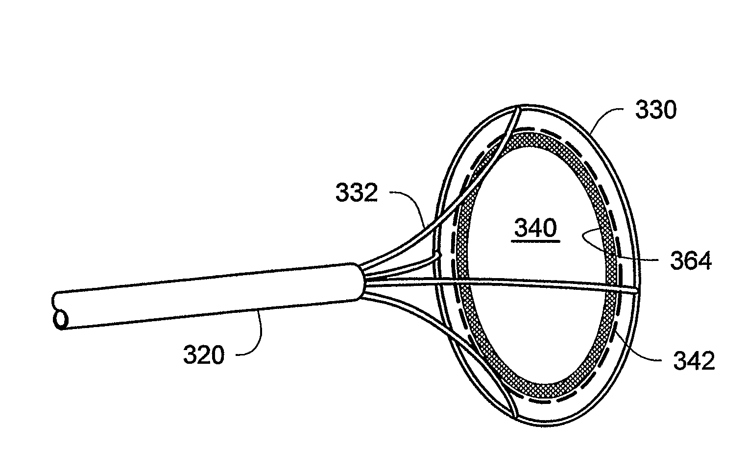
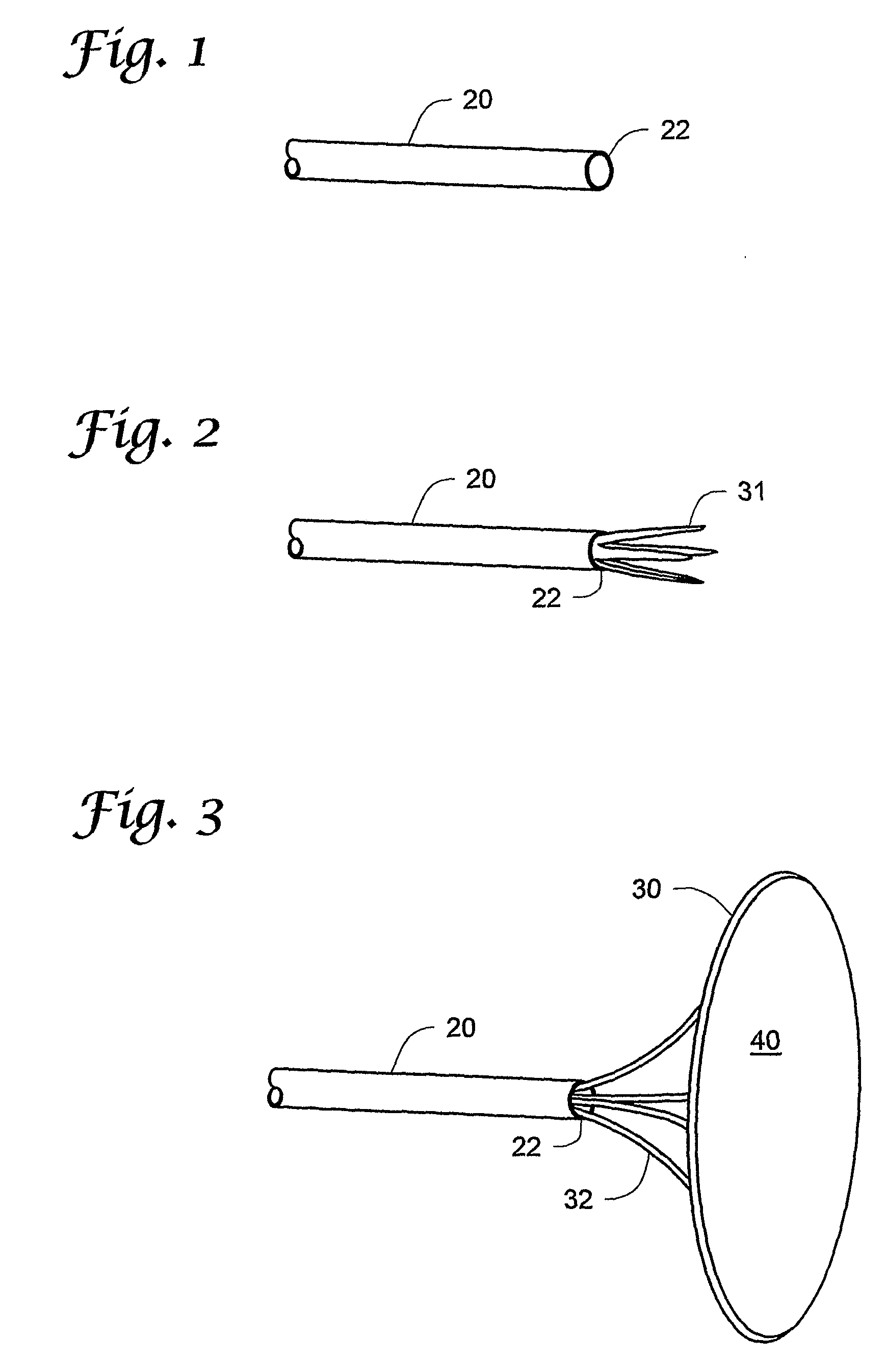
[0049]FIG. 1 is a perspective view of the distal end 22 of an optional delivery sheath 20 that may be used in the apparatus of the present invention. It is preferably in the form of a low profile, flexible tube that can be advanced to the heart via the vasculature over a wire using techniques and devices well known in the art. FIG. 2 is a perspective view of the delivery sheath of FIG. 1 in which a collapsible patch is being deployed out of the distal end 22 with the support of a deployment scaffold 31 that is depicted in its partially collapsed configuration.

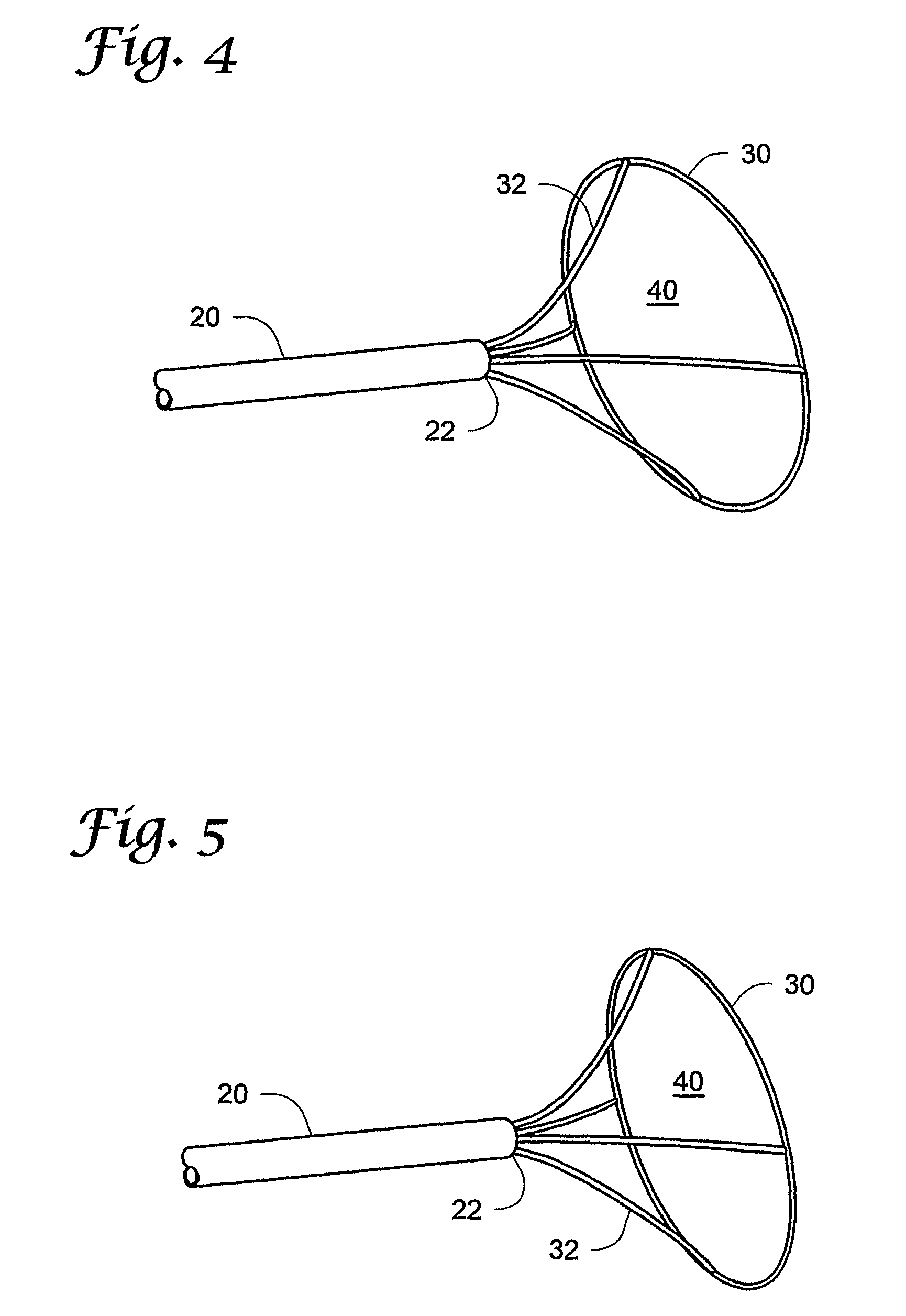
[0050]FIG. ...