Apparatus for combustion of biofuels

Inactive Publication Date: 2009-11-05
HESTIA HEATING PRODS
View PDF0 Cites 6 Cited by
  • Summary
  • Abstract
  • Description
  • Claims
  • Application Information

AI Technical Summary

Benefits of technology

[0015]The burn pot or box is a vee-shaped enclosure that has a longitudinally extending mechanized grate which delimits a floor for the box. Rear and side walls of box are fixedly configured, while the “front” wall comprises the oscillating blade. Generally, combustion air is introduced into the burn chamber via apertures adjacent the mechanized grate, more particularly, a grate adapted for rotation. An oxygen injection manifold runs parallel and adjacent to the rotating grate along a fixed “back” wall of the box. The manifold assembly supplies supplemental concentrated oxygen into the fire zone of the burn box to ensure complete combustion, i.e., maximum conversion of the biofuel. This feature is especially advantageous during startup so as to avoid excess smoking associated with heretofore known conventional biofuel combustion appliances, and in furtherance of providing complete and reliable combustion with all biofuel types, particularly grains, including a fuel characterized by a mixed biomass.
[0016]The burn chamber readily and efficiently converts pelletized, minimally processed, and/or raw biomass into thermal energy for a variety of heating applications. Biomass is introduced into the burn box from a feed system which delivers the fuel to and/or upon a distribution block that distributes the fuel evenly across the burn box, more particularly, evenly and fully across the length of the grate. Characteristically, as the biomass begins to burn, clumps begin to form, thereby interfering in the process of burning the raw fuel down into fine ash, and expelling the ash from the burn box. Minimization, to the point of elimination, of clumping is achieved in great part by the oscillating motion of the blade which selectively, via reciprocation, breaks down any partially burned fuel clumps on the grate into an even

Problems solved by technology

Characteristically, as the biomass begins to burn, clumps begin to form, thereby interfering in

Method used


Image

  • Apparatus for combustion of biofuels
  • Apparatus for combustion of biofuels
  • Apparatus for combustion of biofuels

Examples


Embodiment Construction

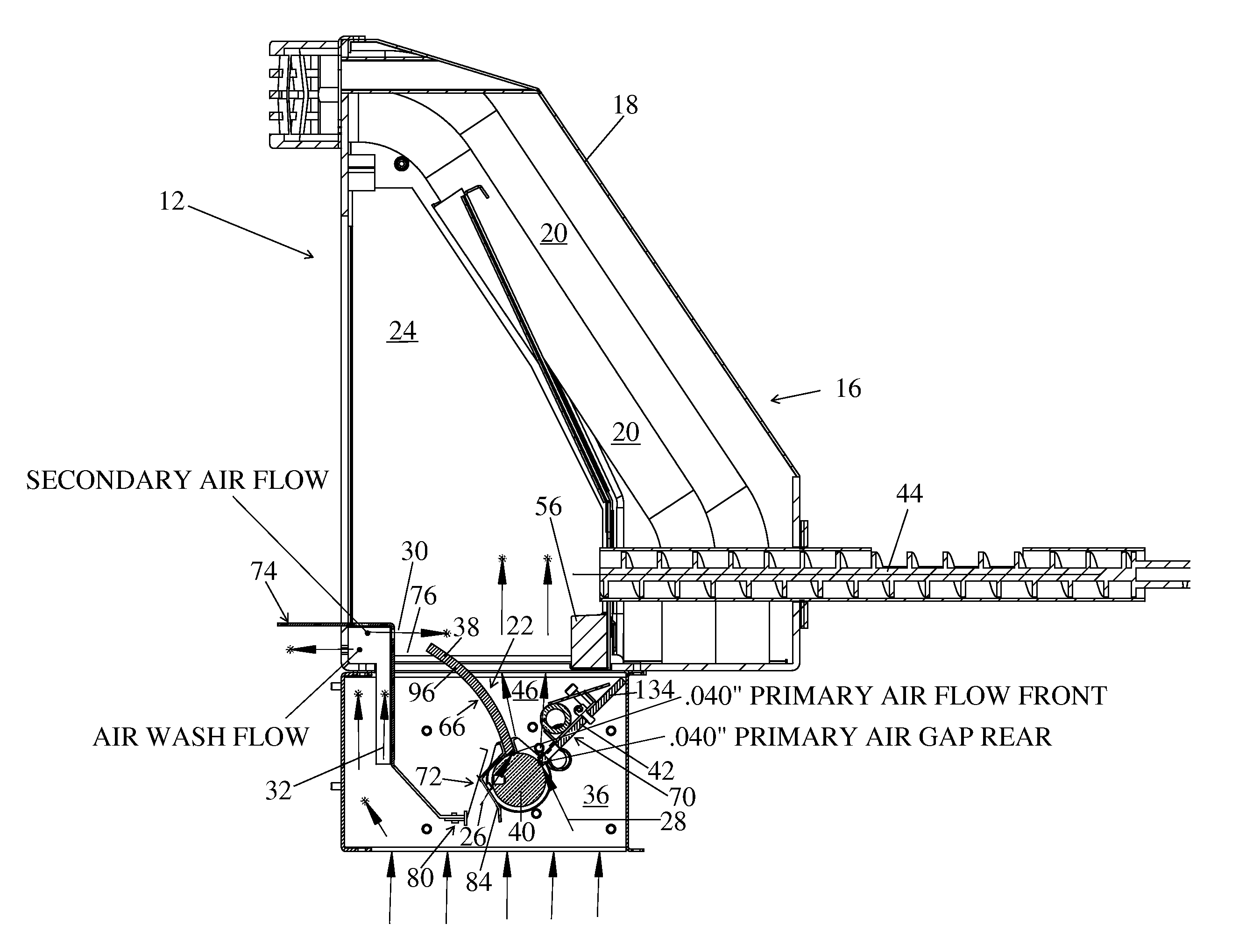
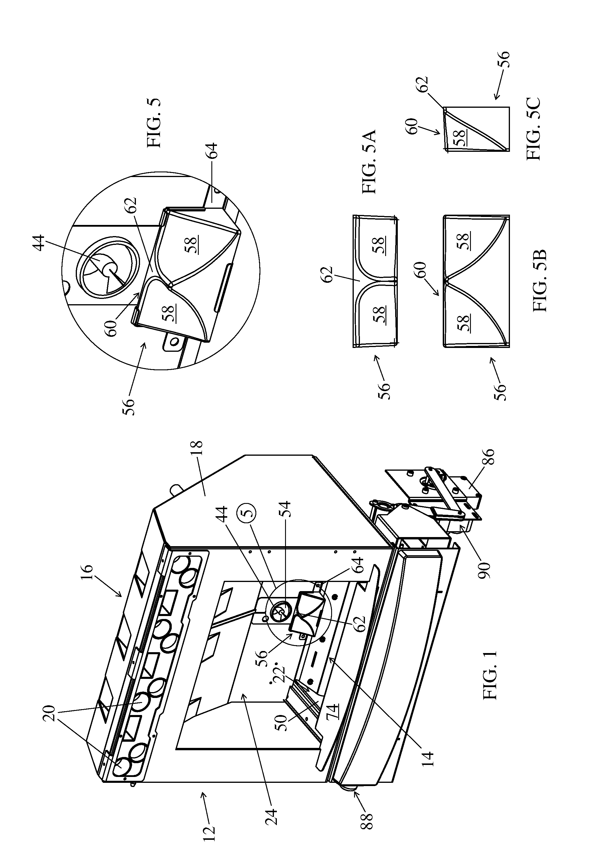
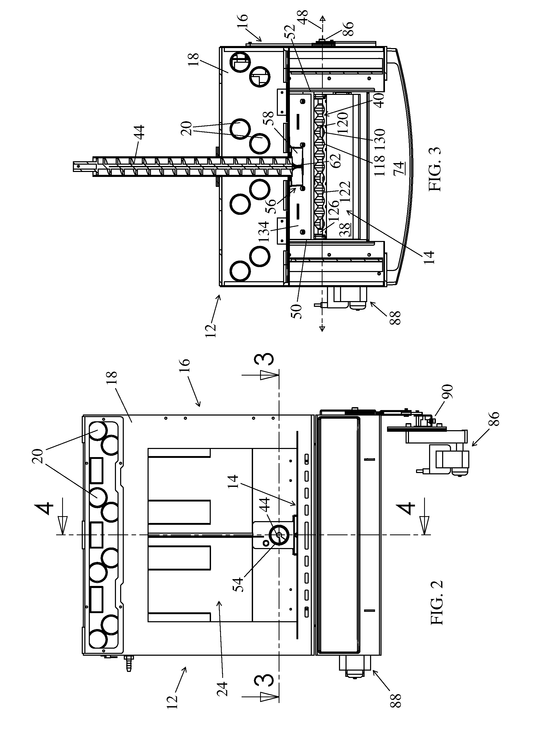
[0041]The subject combustion device, per se and in combination with other elements or features of a heating appliance or the like, is generally depicted in FIGS. 1-4, &6, more particularly, FIGS. 1-4 are generally directed to components of a heating appliance while FIG. 6 is specifically directed to a first combustion chamber assembly embodiment, an alternate, further combustion chamber assembly embodiment depicted in FIG. 11. The remaining figures, namely FIGS. 5&7-10, on the one hand, and FIGS. 12-14 on the other hand, depict advantageous features of contemplated appliance assemblies, and / or subassemblies of the subject invention, namely those associated with the combustion assembly of FIG. 6 or FIG. 11, respectively.

[0042]While the device of the subject invention, more particularly, the biomass fuel burner is especially well suited for inclusion in a residential or commercial heating appliance, e.g., a stove, it need not be so limited in utility. Contemplated applications for the...


PUM


Abstract

An apparatus for combustion of biomass is provided. The apparatus generally includes opposingly paired sidewalls, a fixed panel traversing the opposingly paired sidewalls, an actuatable panel opposite the fixed panel, and a fuel platform supported by a panel of either of the panels. A portion of the fuel platform is reversibly receivable through a portion of a panel opposite the panel supporting the fuel platform in furtherance of fuel conditioning upon actuation of the actuatable panel.

Description

[0001]This is a continuation-in-part application filed under 35 U.S.C. §53(b) claiming priority under 35 U.S.C. §120 of co-pending U.S. patent application Ser. No. 11 / 550,494 filed Oct. 18, 2006.TECHNICAL FIELD[0002]The present invention generally relates to biofuel burning heating devices, more particularly, to devices for the efficient production of thermal energy from biofuels such as pelletized, minimally processed, and / or raw biomass.BACKGROUND OF THE INVENTION[0003]With the further increasing costs of gas and fuel oil, in combination with an ever increasing social consciousness directed to conservation and recycling, further attention is being directed to alternate fuel sources such as wood and other solid / semi-solid combustibles or combustible residues. A resurgence of interest and attention is being given to biofuels, biofuel combustion processes and biofuel combustion devices.[0004]“Biofuel” is a term generally understood to embrace any fuel derived from biomass, namely, re...

Claims


Application Information

Patent Timeline
IPC IPC(8): F23G5/44F23K3/00
CPCF23B1/16F23B30/10F23L9/02F23H9/02F23L1/02F23B60/02
Inventor NELSON, ERIC W.MADSEN, JOHN L.ORVIS, WILLIAM D.
Owner HESTIA HEATING PRODS
Why Eureka
Try Eureka