Power output apparatus and hybrid vehicle

a technology of power output apparatus and hybrid vehicle, which is applied in the direction of electric propulsion mounting, battery/cell propulsion, gearing, etc., can solve the problems of complex configuration and inability to compact, and achieve the effects of reducing power loss, improving productivity, and reducing costs

Inactive Publication Date: 2009-12-10
TOYOTA JIDOSHA KK
View PDF1 Cites 17 Cited by
  • Summary
  • Abstract
  • Description
  • Claims
  • Application Information

AI Technical Summary

Benefits of technology

[0007]In view of this, an object of the present invention is to provide a power output apparatus and a hybrid vehicle having the same which have simple and compact configurations, and are excellent in mountability. In addition, an object of the present invention is to provide a power output apparatus and a hybrid vehicle having the same capable of improving power transmission efficiency in a wider driving area.
[0020]The present invention is directed to a hybrid vehicle. The hybrid vehicle includes any one of power output apparatus described above, and includes drive wheels driven by a power from the drive shaft. Since the power output apparatus mounted in the hybrid vehicle is simple and compact with excellent mountability, and can improve power transmission efficiency over a wider driving area, the hybrid vehicle can favorably improve fuel consumption and drive performance.

Problems solved by technology

However, their configurations are complicated and impossible to make compact, so there are some problems in mountability to vehicle.

Method used


Image

  • Power output apparatus and hybrid vehicle
  • Power output apparatus and hybrid vehicle
  • Power output apparatus and hybrid vehicle

Examples


Embodiment Construction

[0034]Hereinafter, the best mode for carrying out the invention will be described with reference to embodiments.

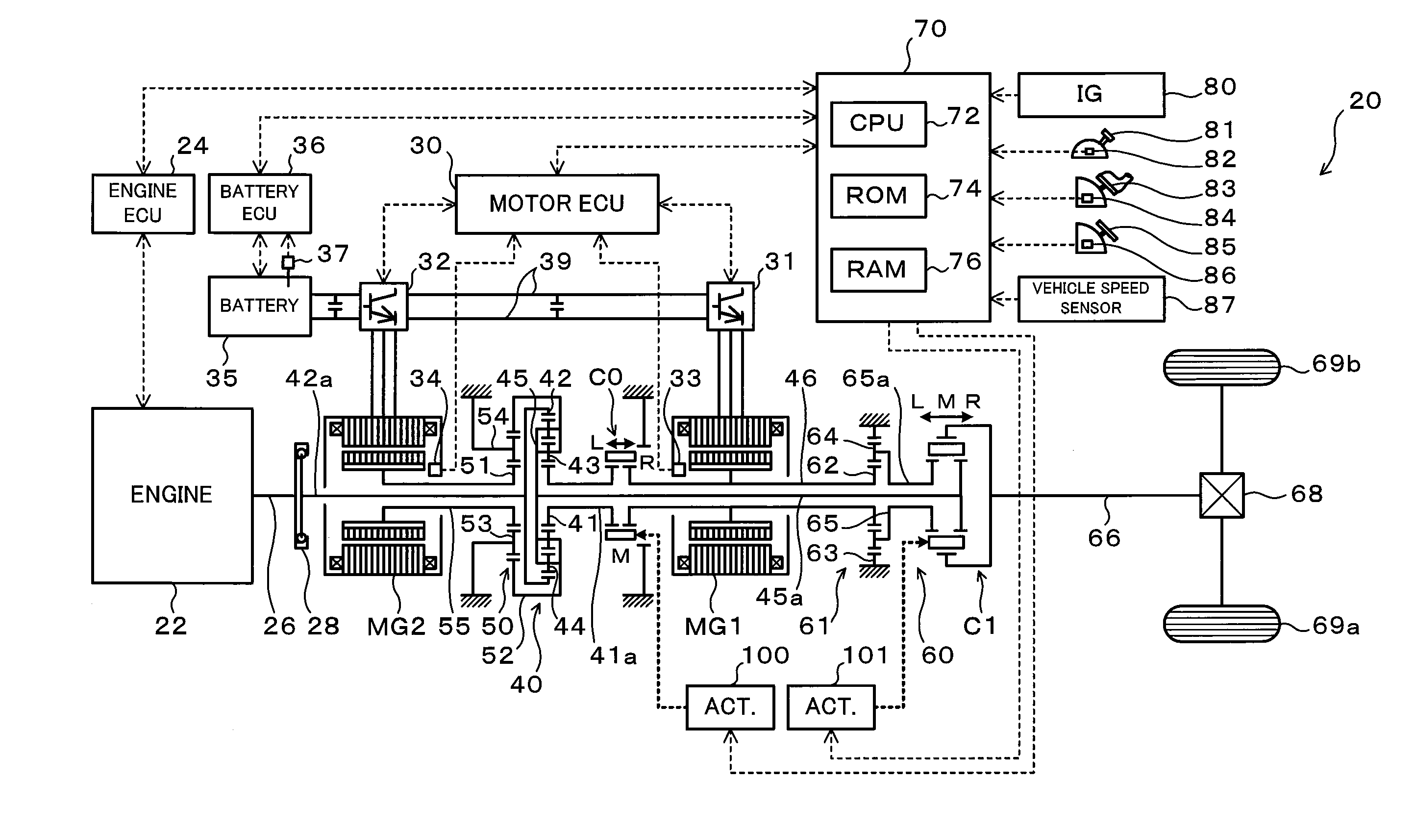
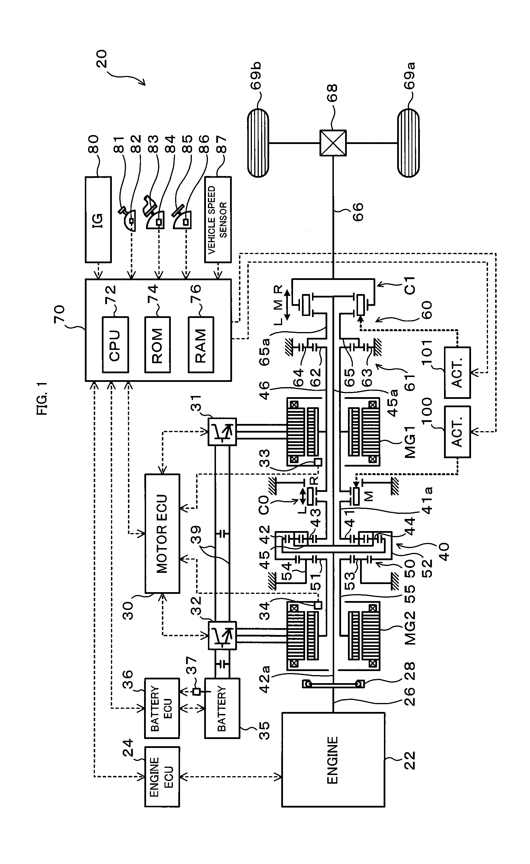
[0035]FIG. 1 is a schematic configuration view of a hybrid vehicle 20 in accordance with a present embodiment of the present invention. The hybrid vehicle 20 shown in the same figure is configured as a rear-wheel-drive vehicle, and includes an engine 22 arranged in a vehicle front portion; a power distribution and integration mechanism (differential rotation mechanism) 40 connected to a crankshaft 26 which is an output shaft of the engine 22; a generatable motor MG1 connected to the power distribution and integration mechanism 40; a generatable motor MG2 arranged coaxially with the motor MG1 and connected to the power distribution and integration mechanism 40 through a reduction gear mechanism 50; a transmission 60 capable of transmitting power from the power distribution and integration mechanism 40 to a drive shaft 66 with a change in speed ratio; and a hybrid electronic...


PUM


Abstract

A hybrid vehicle includes an engine, motors, and a power distribution and integration mechanism that are coaxially arranged with respect to each other. The hybrid vehicle also includes a transmission including a transmission differential rotation mechanism that has a sun gear as an input element connected to a sun gear which is a first element of the power distribution and integration mechanism, a ring gear as a fixing element, and a carrier as an output element, and that is configured such that these three elements can differentially rotate with each other; and a clutch as a coupling mechanism capable of selectively coupling the sun gear of the transmission differential rotation mechanism and the carrier which is the second element of the power distribution and integration mechanism with a drive shaft.

Description

TECHNICAL FIELD[0001]The present invention relates to a power output apparatus for outputting power to a drive shaft and a hybrid vehicle having the same.BACKGROUND ART[0002]Conventionally, as such a power output apparatus, there has been known a power output apparatus including an internal combustion engine, two motors, a so-called ravigneaux planetary gear mechanism, a parallel shaft-type transmission capable of selectively coupling two output elements of the planetary gear mechanism to an output shaft (for example, see Patent Document 1). In addition, conventionally, there has been known a power output apparatus including a planetary gear device having an input element connected to an internal combustion engine and two output elements; and a parallel shaft-type transmission having a countershaft connected respectively to a corresponding output element of the planetary gear mechanism (for example, see Patent Document 2). According to the power output apparatus, each of the two out...

Claims


Application Information

Patent Timeline
Patent Type & Authority Applications(United States)
IPC IPC(8): B60K6/445B60K6/40B60L50/16
CPCB60K1/02B60L2200/26B60K6/387B60K6/40B60K6/445B60K6/547B60L11/123B60L11/14B60L2240/423B60L2240/486B60L2270/145B60W10/06B60W10/08B60W10/115B60W20/00B60W2520/10B60W2540/10B60W2540/12B60W2540/16B60W2710/083F16H3/728F16H2037/0873F16H2200/2007F16H2200/201F16H2200/2041F16H2200/2064F16H2200/2097Y02T10/6217Y02T10/6286Y02T10/646Y02T10/7077Y02T10/648Y02T10/6239B60K6/365B60L50/61B60L50/16Y02T10/62Y02T10/64Y02T10/7072Y02T10/70B60W10/02B60W20/10
Inventor OBA, HIDEHIROIDESHIO, YUKIHIKO
Owner TOYOTA JIDOSHA KK
Why Eureka
Try Eureka