Method of erecting a building structure in a water basin

Inactive Publication Date: 2009-12-31
TECHNION RES & DEV FOUND LTD
View PDF12 Cites 28 Cited by
  • Summary
  • Abstract
  • Description
  • Claims
  • Application Information

AI Technical Summary

Benefits of technology

[0018]An object of the invention is the task of finding a method of creating a building structure to be installed on the basin floor wherein the base for erecting the structure would be an element of such a block and this block would be placed on the basin floor in such a way, and would be fixed i

Problems solved by technology

However, this method is highly labour-consuming and not economical enough since it requires great quantities of inert material and loading the material on floating facilities and delivering it to a building site.
The main drawback of such method is the impossibility of using it for erecting stationary, large-sized heavy structures.
In addition, this method is not economical enough since it requires the use of great quantities of excessive metal (material of ballastable modules) which is of no direct relation to the structure being created.
Another drawback is the necessity of connecting the modules with one another under water which complicates the method significantly.
And, finally, availability of several modules placed one on top the other affects significantly the reliability of the structure when erected at seismically dangerous areas, at

Method used


Image

  • Method of erecting a building structure in a water basin
  • Method of erecting a building structure in a water basin
  • Method of erecting a building structure in a water basin

Examples


Example

[0033]The building structure is created in the following way.

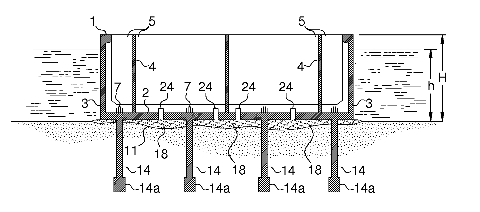
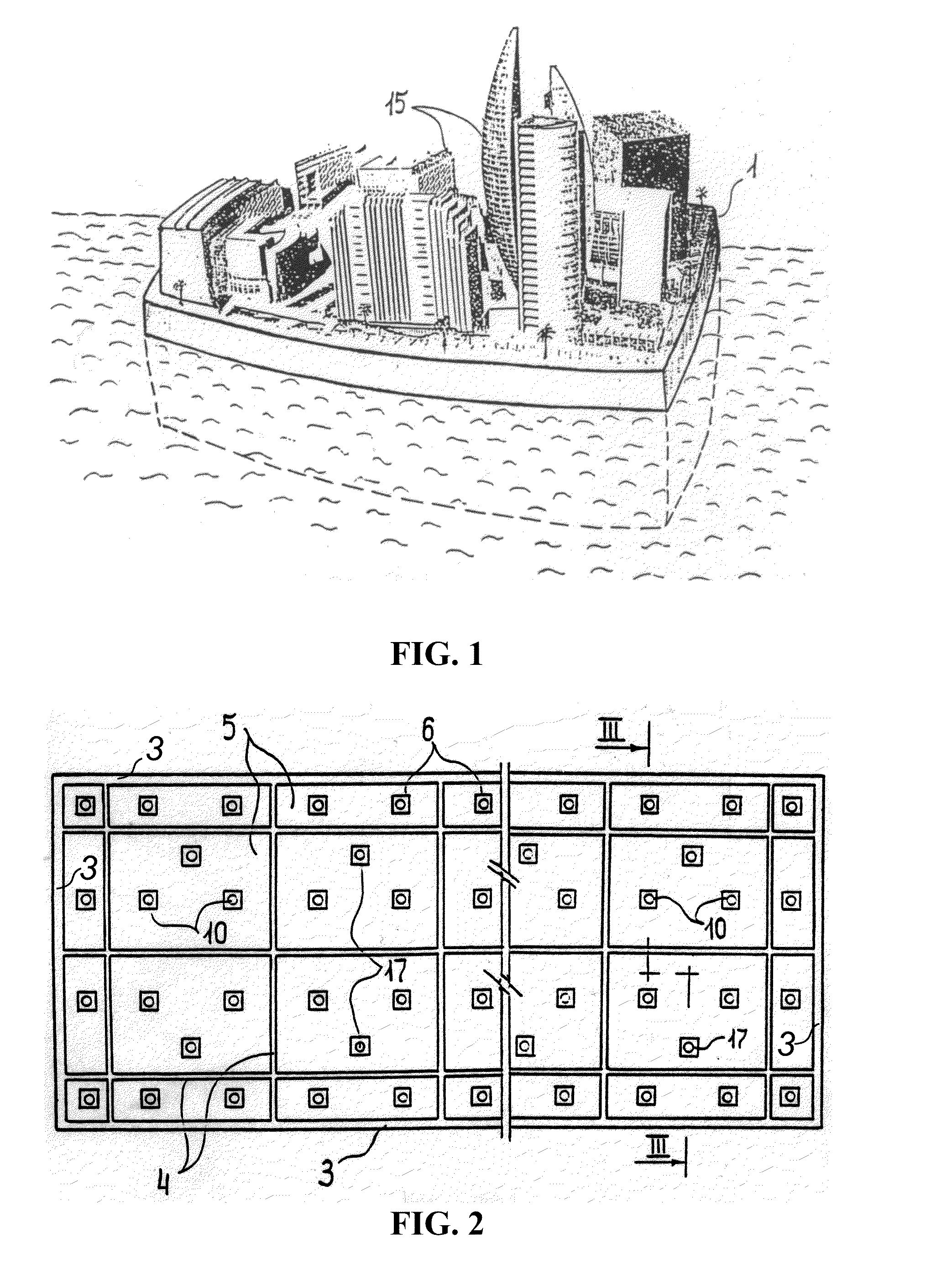
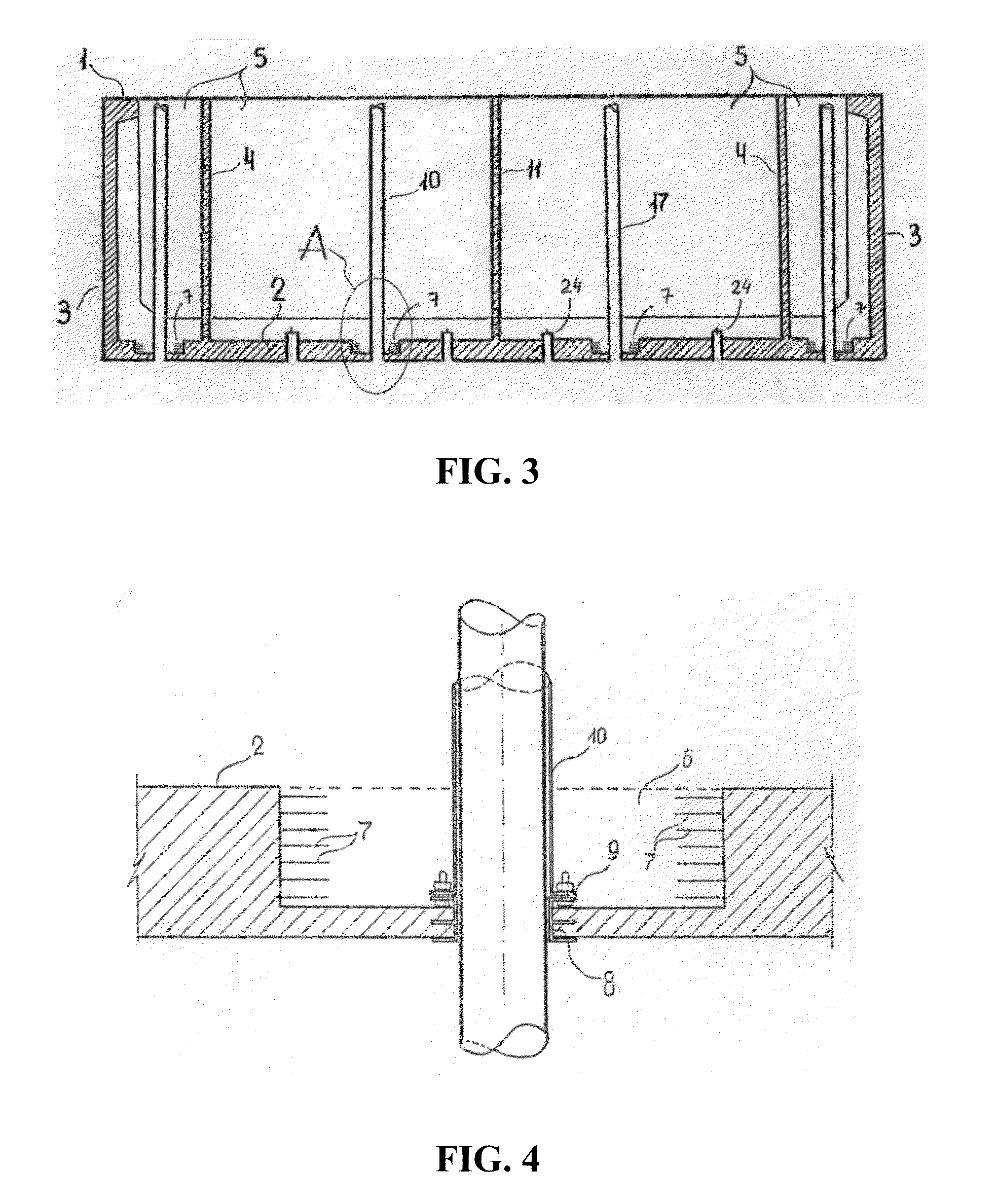
[0034]Reinforced-concrete pan-shaped floating block 1 (FIG. 1) is prefabricated at a factory. Block 1 comprises a base member-a bottom which is essentially one-piece bedplate 2 (FIG. 2, 3), walls 3 that embrace hermetically bedplate 2 around its perimeter and internal upright water-tight partitions 4 dividing the working area between walls 3 into individual sections 5. In one version of embodiment the invention (not shown) partitions 4 are absent. Made in bedplate 2 over its entire area there grooves 6 (FIG. 4, 5) with reinforcing bars 7. Made in grooves 6 are through holes (not shown). In each of these hole branch pipe 8 is concreted with flange 9 located in groove 6. Upright process pipes 10 are connected with branch pipes 8 by means of flanges 9. Height “H” of the block (FIG. 6-9), in particular of walls 3, partitions 4 and process pipes 10 exceeds the water depth “h” at water site 23 where building structure 15 (FIG. 1...


PUM


Abstract

The present invention provides a method of creating a building structure to be installed on a basin floor wherein the base for erecting the structure would be an element of such a block and this block would be placed on the basin floor in such a way, and would be fixed in position relative to it in such a manner, that this base could be used as a foundation for stationary, large-sized heavy structures and also to ensure the possibility of using the block elements as members of the structure being erected and thus to increase the economic efficiency of the method.

Description

CROSS-REFERENCE TO RELATED APPLICATION[0001]This application is based upon and claims priority of co-pending, commonly assigned U.S. Provisional Patent Application Ser. No. 61 / 049,302, filed Apr. 30, 2008, which is incorporated herein in its entirety.FIELD OF THE INVENTION[0002]The invention relates to the field of construction, more specifically, to erection of individually located large building structures such as residential buildings, hotel complexes, industrial projects, airdromes, artificial islands etc., on the sea floor in shallow water or in another water basin.BACKGROUND OF THE INVENTION[0003]There is a widely known method of creating building structures in water wherein a preset area of a water basin is filled with some inert material to exceed the water level and then a building structure is erected on the surface of the formed island used as a base.[0004]However, this method is highly labour-consuming and not economical enough since it requires great quantities of inert...

Claims


Application Information

Patent Timeline
IPC IPC(8): E02D23/02
CPCE02D27/20E02D23/02
Inventor GRINBERG, VYACHESLAVDAVIDOVICH, ILYAYAKHINS, SAMUILKOVLER, KONSTANTIN
Owner TECHNION RES & DEV FOUND LTD
Why Eureka
Try Eureka