Suspension packaging assembly

a suspension packaging and assembly technology, applied in the direction of packaging, packaging, packaging goods, etc., can solve the problems of difficult and expensive automation of assembly lines, complex suspension packaging devices, and suspension packaging devices noted above, etc., to achieve the effect of easy assembly, low cost of certain processes, and low cos

Inactive Publication Date: 2009-11-05
CLEARPAK
View PDF92 Cites 24 Cited by
  • Summary
  • Abstract
  • Description
  • Claims
  • Application Information

AI Technical Summary

Benefits of technology

[0008]One aspect of the present invention includes the recognition that the cost of certain processes used for manufacturing known suspension packaging devices can be sufficiently high to prohibit the use of suspension packaging with many common goods. For example, it has been known to permanently bond resilient sheet material to cardboard frames in order to produce suspension packaging devices in a variety of configurations for suspending articles within boxes. However, it is difficult and expensive to automate an assembly line for bonding such films to cardboard substrates or to perform such an assembly process manually. Additionally, certain known suspension packaging devices can be complex and require excessive training in order to properly assemble the devices. Thus, it is desirable to provide a packaging assembly which is inexpensive to manufacture and easy to assemble.
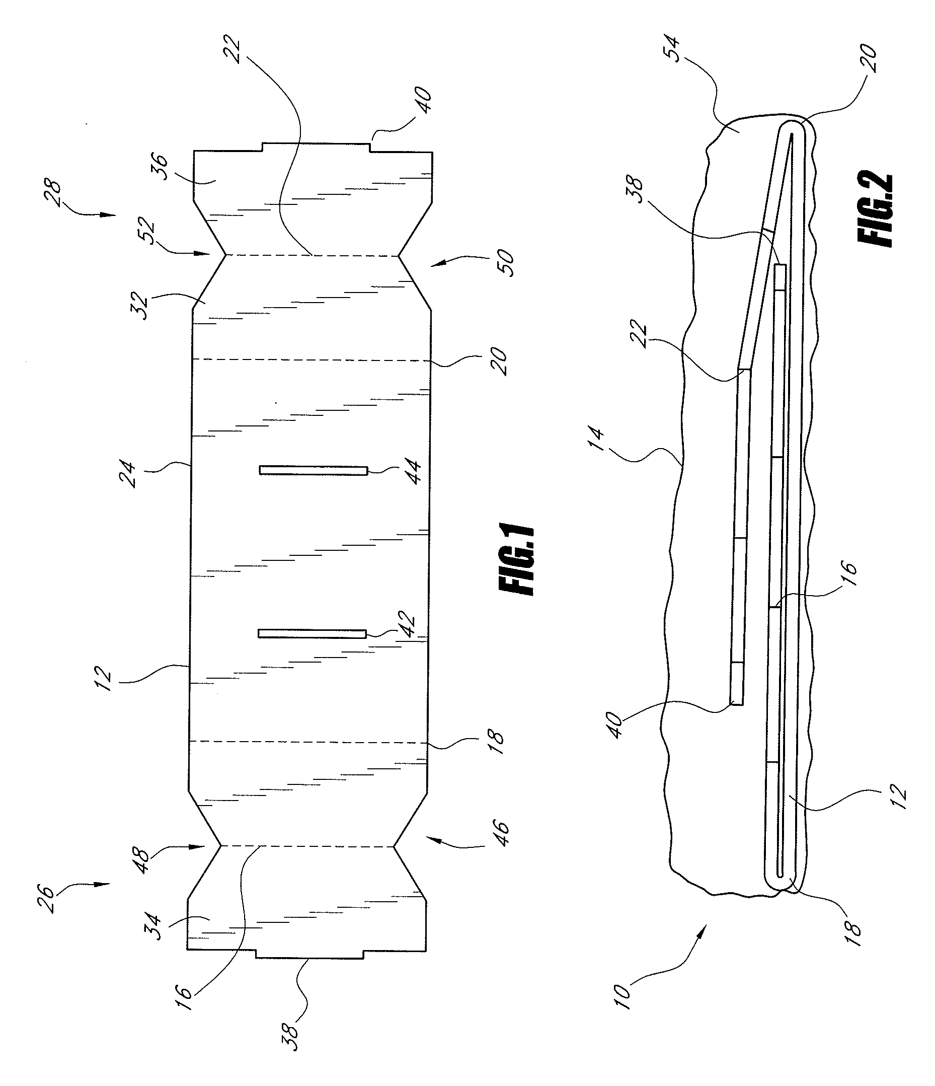
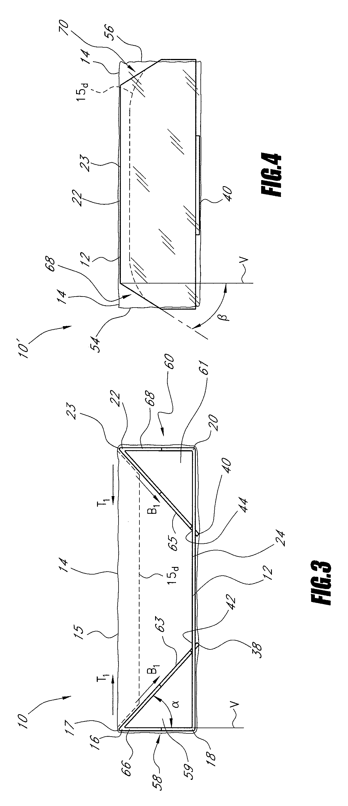
[0010]In one mode, a frame member for a packaging assembly includes a plurality of fold lines configured to form at least one foldable portion. The foldable portion is foldable between at least a first position and a second deployed position in which the foldable portion forms a releasably engageable peripherally extending structure. By providing the frame member with a foldable portion as such, the frame member can be placed within a sleeve and folded to the second position, thus expanding the foldable portion and tightening the sleeve. As such, the frame member provides enhanced flexibility in the manner in which it can be used as a suspension packaging device.
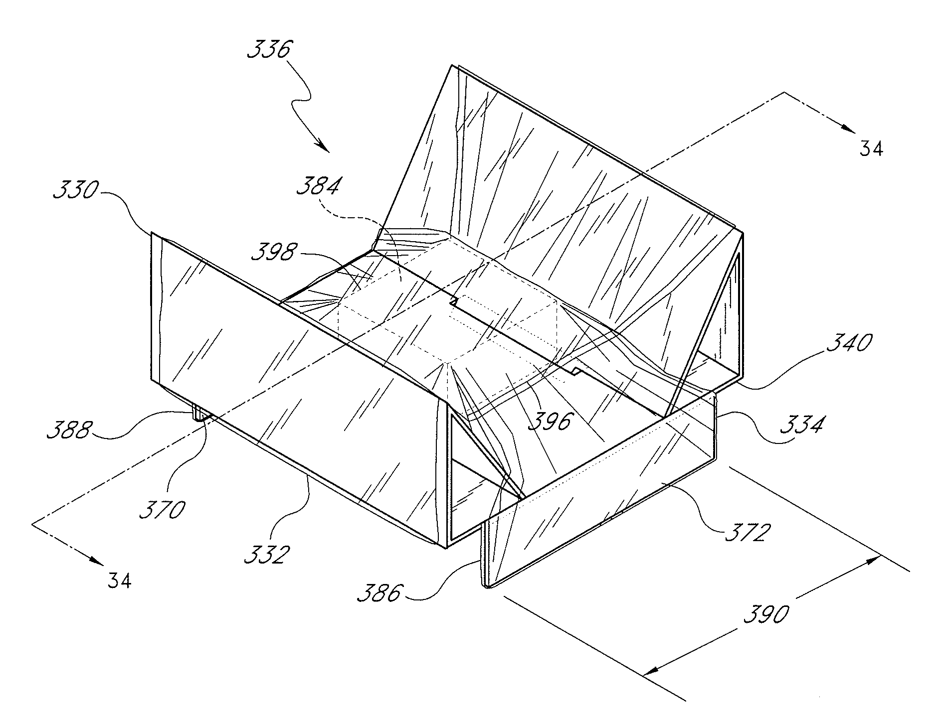
[0011]In another mode, a packaging assembly includes a first frame member having a plurality of fold lines and a retention sleeve configured to receive the frame member. The plurality of fold lines are configured to form at least one foldable portion which is foldable between at least a first position and a second deployed position in which the foldable portion forms a peripherally extending structure within the sleeve when the frame member is received within the sleeve. By providing the frame member with a foldable portion as such, the present invention provides a suspension packaging assembly that achieves several advantages over known suspension packaging devices.
[0012]For example, since the packaging device, according to the present invention, includes a retention sleeve and a frame member having a foldable portion configured to form a peripherally extending structure within the sleeve, it is not necessary to bond the sleeve to the frame. Thus, the packaging device does not require the expensive and time consuming steps associated with permanently bonding the retention member to the frame member. Additionally, since the retention member is not required to be permanently bonded to the frame member, the manufacturing of these individual components can be performed at facilities that are located geographically distant from each other. For example, where a polymer film is used as the retention sleeve, the polymer film can be manufactured in a distant country and shipped to an assembly or a distribution facility without incurring prohibitive shipping costs since polymer film materials typically do not have great bulk and are relatively lightweight. However, the frame members are typically formed of corrugated cardboard; a material which has relatively great bulk and weight. Thus, it can be prohibitively expensive to manufacture corrugated cardboard components at a great distance from the distribution facility. By incorporating a retention sleeve which is not permanently bonded to the frame member, the individual components of the packaging device according to the present invention can be manufactured at distant geographic locations. Each component can thus be manufactured with the greatest economic efficiency, i.e., the individual components can be manufactured at locations, which may be in foreign countries, that offer the least expensive combination of labor, raw materials, and transportation to the distribution facility.
[0014]As noted above, it is advantageous to utilize with suspension packaging devices retention members that are not permanently bonded to the frame members. Thus, by providing the retention member with pockets, according to the present aspect of the invention, the packaging device does not require the costly and time consuming manufacturing steps required for bonding a retention member to a frame member. Rather, the pockets formed on the retention member can be formed, for example, but without limitation, by a simple heat sealing process, thus eliminating the need for adhesives, specialized machinery for dispensing adhesives, and the time consuming steps required for properly bonding the retention member to the frame member with an adhesive. Additionally, the packaging assembly can be conveniently disassembled for recycling or reuse.
[0015]Another aspect of the present invention involves the recognition that the economic impact of forming pockets by heat sealing, rather than adhesive, reduces the costs of such packaging devices to such an extent that these packaging devices can now be used with a wider variety of less expensive goods that benefit from such protective packaging.

Problems solved by technology

However, it is difficult and expensive to automate an assembly line for bonding such films to cardboard substrates or to perform such an assembly process manually.
Additionally, certain known suspension packaging devices can be complex and require excessive training in order to properly assemble the devices.
For example, the suspension packaging devices noted above, which incorporate a resilient polymer film member permanently bonded to a rigid cardboard substrate, are not easily reusable or recyclable.
The process of separating the film from the rigid substrate permanently damages the backing member and / or the film since the film is permanently bonded to the backing.
Thus, not only is it difficult to recycle the materials used for constructing the packaging device, it is difficult to reuse either the film or the backing individually since these materials are damaged upon the removal of the film from the backing.

Method used


Image

  • Suspension packaging assembly
  • Suspension packaging assembly
  • Suspension packaging assembly

Examples


Embodiment Construction

[0060]An improved packaging assembly is disclosed herein. The packaging assembly includes an improved structure which provides an easy-to-assemble and less expensive alternative to known suspension packaging devices.

[0061]In the following detailed description, terms of orientation such as “upper,”“lower,”“longitudinal,”“horizontal,”“vertical,”“lateral,”“midpoint,” and “end” are used here to simplify the description in the context of the illustrated embodiment. Because other orientations are possible, however, the present invention should not be limited to the illustrated orientation. Those skilled in the art will appreciate that other orientations of the various components described above are possible.

[0062]FIGS. 1-4 illustrate a packaging assembly configured in accordance with an embodiment of the present invention. With initial reference of FIGS. 1-4, a frame member 12 (FIG. 1) and a retention sleeve 14 (FIG. 2) cooperate to form a packaging assembly 10 (FIGS. 2-4).

[0063]With refe...


PUM


Abstract

A packaging assembly includes a frame member and a retention member which is not permanently affixed to the frame member. The frame member can include a variety of features which allow the retention member to be tightened around an article to be packaged and thus protected from shocks and impacts during transport, display, and / or retail use. The retention member can be formed as a sleeve or with pockets for engaging the frame member.

Description

PRIORITY INFORMATION[0001]This application is a Continuation Application of U.S. patent application Ser. No. 10 / 726,256, filed Dec. 2, 2003, which is a Divisional Application of U.S. patent application Ser. No. 09 / 690,790, filed Oct. 17, 2000, now U.S. Pat. No. 6,675,973 based on and claims priority to U.S. Provisional Patent Application No. 60 / 227,724, titled SUSPENSION PACKAGING ASSEMBLY, filed Jul. 31, 2000, the entire contents of which is hereby expressly incorporated by reference.BACKGROUND OF THE INVENTION[0002]1. Field of the Invention[0003]The present invention is directed to a packaging assembly. In particular, the present invention is directed to a suspension packaging assembly that includes a retention member and a frame member.[0004]2. Description of the Related Art[0005]Protective packaging devices are often used to protect goods from shocks and impacts during shipping or transportation. For example, when transporting articles that are relatively fragile, it is often de...

Claims


Application Information

Patent Timeline
Patent Type & Authority Applications(United States)
IPC IPC(8): B65D85/30B65D5/50B65D81/07
CPCB65D81/075B65D5/5028
Inventor MCDONALD, JOHNCOMERFORD, MYLESCOMERFORD, FRANK
Owner CLEARPAK
Why Eureka
Try Eureka