Method and apparatus for manufacturing an optical cable and cable so manufactured

a manufacturing method and technology of optical cables, applied in the direction of non-electric welding apparatus, instruments, fluid removal, etc., can solve the problems of metal deformation, difficult method, high temperature and high pressure in the retaining spa

Active Publication Date: 2010-01-21
PRYSMIAN CAVI E SISTEMI ENERGIA
View PDF15 Cites 10 Cited by
  • Summary
  • Abstract
  • Description
  • Claims
  • Application Information

AI Technical Summary

Benefits of technology

[0032]In view of the above definition, the excess fiber length (EFL) can be easily measured in the finished cable.
[0035]Different time span can be used in view of specific manufacturing needs, for example, a shorter time span can be useful for achieving a particularly high constancy of the EFL value along the cable, where the specific cable application so requires; or at high manufacturing speed, while a longer time span can enable the use of simpler measurement devices and control apparatus, or be used at low manufacturing speed.
[0046]Preferably, because in such case the fiber is subject to tensile stress after its winding inside the tube on the congruence pulley, the subsequent tube shortening should be made immediately afterwards the fiber and tube leave the congruence pulley, in order to reduce the time in which the fiber is exposed to such tensile stress.
[0052]Preferably, the step of adjusting the resulting EFL by controlling the elongation of the metal tube is effected by a speed adjustment on the apparatus drawing the tube. More particularly, the elongation of the tube is effected by increasing the drawing speed of the tube when the resulting EFL is higher then the predetermined one, or by reducing the drawing speed of the tube when the resulting EFL is lower than the predetermined one.
[0084]Optionally, upstream from the first pulling device, a die can be provided for equalizing the dimension or the surface of the metal tube. Said die can also provide a reduction of the metal tube diameter.
[0086]Within the present description and claims, by capstan we mean a motor driven pulley around which the cable or tube is wound by at least one turn. If needed, such capstan includes a caterpillar acting on the cable or tube immediately downstream the drum or pulley to pull the cable or tube with a force high enough to generate a friction preventing slippage of the cable or tube on the surface of the drum or pulley.

Problems solved by technology

The rotation of the frictional wheel produces high temperatures and high pressures in the retaining space, which plastically deform the metal.
The Applicant observed that this method is difficult to be carried out, and the results in term of excess fiber length are unreliable.

Method used


Image

  • Method and apparatus for manufacturing an optical cable and cable so manufactured
  • Method and apparatus for manufacturing an optical cable and cable so manufactured
  • Method and apparatus for manufacturing an optical cable and cable so manufactured

Examples


example 1

Comparative

[0151]An aluminium tube having outer diameter of 4.6 mm and wall thickness of 1.7 mm was produced, housing 6 optical fibers.

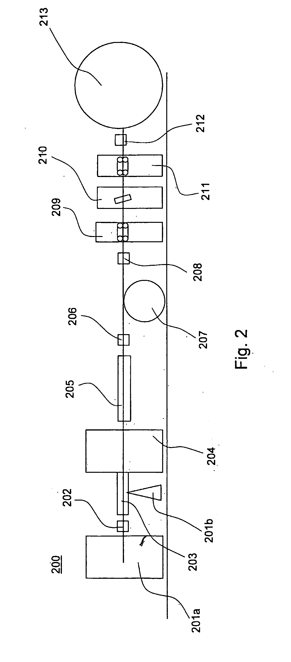
[0152]The tube was produced with a Conform™ machine, and was shortened by corrugation.

[0153]A constant pulling force of 40 kgf was applied downstream from the corrugator by a caterpillar.

[0154]A length of 10 km of optical fiber housing tube was produced.

[0155]The desired EFL was of 0.7%.

[0156]The resulting metal tube provided an average EFL of 0%, that means that the shortening due to the corrugation was completely cancelled by the subsequent drawing.

[0157]Frequent breaks were also observed during the production.

example 2

Comparative

[0158]An aluminium tube having outer diameter of 4.95 mm and a wall thickness of 1.25 mm was produced, housing 6 optical fibers.

[0159]The tube was produced with a Conform™ machine.

[0160]The 6 optical fibers were supplied into the tube while it was formed together with a gel Seppigel® H-LAV (Seppigel® is a registered trademark of Seppic).

[0161]The tube was cooled by water spraying.

[0162]After cooling, the tube was shortened of 0.9% by corrugation.

[0163]The corrugation was applied with the following parameters:[0164]pitch: 10 mm;[0165]width: 3 mm; and[0166]depth: 0.25 mm.

[0167]The shortened tube was then elongated of 0.2% by applying a pulling force of 20 kgf downstream from the corrugator.

[0168]Said pulling force was applied by a motor-driven caterpillar, which operation was controlled to maintain the pulling force substantially constant (±10%)

[0169]A length of 6 km of optical fiber housing tube was produced.

[0170]The desired EFL was of 0.7%.

[0171]The resulting EFL was fou...

example 3

Invention

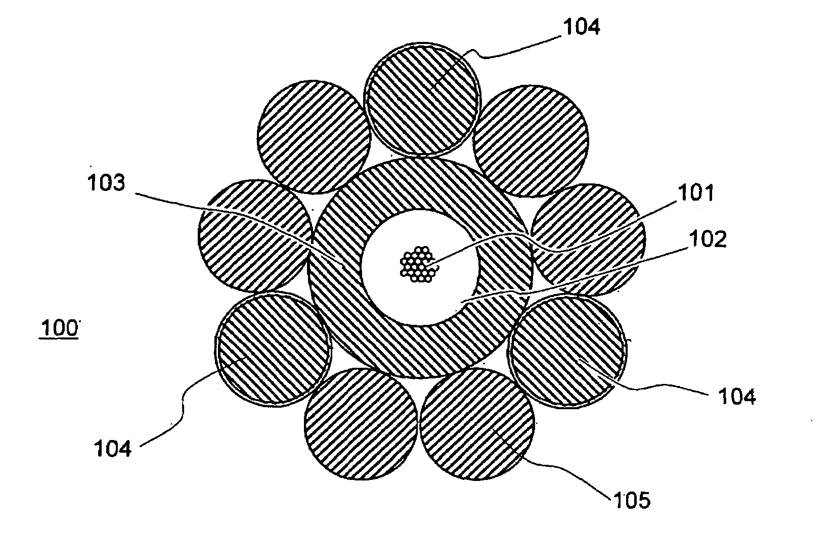
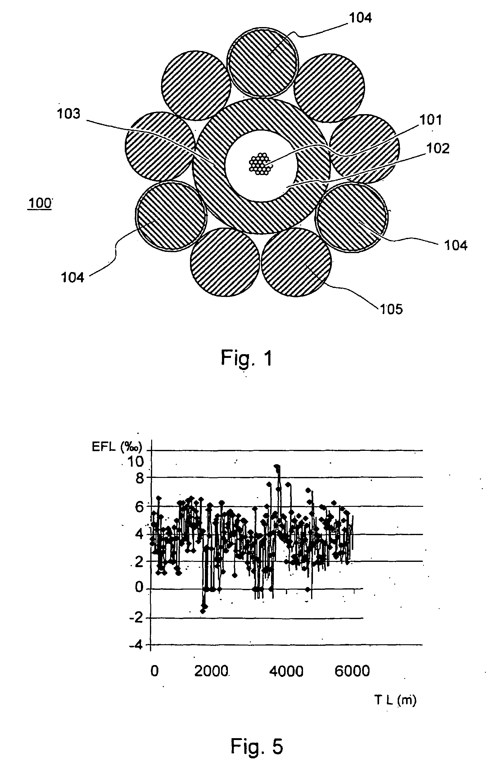
[0172]An aluminium tube having an outer diameter of 5.6 mm and a wall thickness of 1.8 mm was produced, housing 24 optical fibers.

[0173]The fibers were provided together with a gel Seppigel® H-LAV

[0174]The tube was cooled by water spraying.

[0175]After cooling, the tube was shortened of 0.9% by corrugation.

[0176]The corrugation was applied with the following parameters:[0177]pitch: 11 mm;[0178]width: 3.5 mm; and[0179]depth: 0.3 mm.

[0180]The shortened tube was then elongated of 0.2% by applying a pulling force downstream from the corrugator.

[0181]Said pulling force was applied by a motor-driven caterpillar. The operation of said caterpillar was controlled to vary the pulling speed as a function of the EFL resulting from the measurements of the tube length measured by the forth encoder downstream from the elongation and of the fiber length measured by the first encoder, said lengths being passed in the same period of time (e.g. 40 m / min).

[0182]A length of 2.6 km of optical fib...


PUM

PropertyMeasurementUnit
depthaaaaaaaaaa
depthaaaaaaaaaa
internal diameteraaaaaaaaaa

Abstract

A method and apparatus for manufacturing an optical cable comprising at least one metal tube housing at least one optical fiber and having a predetermined excess fiber length (EFL) is described. In this method the metal tube is plastically deformed and shortened by a predetermined amount (St) greater than the predetermined EFL and is plastically deformed after shortening to provide a controlled elongation thereof so as to reach the predetermined excess fiber length. An optical cable so manufactured has a local excess fiber length (EFL) varying of or less than 0.2% along the longitudinal extension of the cable with respect to an average EFL of the cable.

Description

BACKGROUND OF THE INVENTION[0001]The present invention relates to a method for manufacturing an optical cable, to an apparatus for said manufacturing and to an optical cable comprising at least one metal tube housing at least one optical fiber.[0002]The protection of optical fibers by housing in a metal tube finds application in aerial, underground and underwater cable.[0003]Typically, the metal tube encloses a single fiber or several optical fibers, preferably gathered in a multi-fiber bundle. Metals, such as steel, aluminium, aluminium alloys or copper, can be used to manufacture the tube.PRIOR ART[0004]One method for providing a metal tube around one or more optical fibers comprises the step of shaping a metal tube with a longitudinal slit, said slit being sealed after the positioning of the optical fibers in the tube. See, for, example, U.S. Pat. No. 6,522,815 (in the name of Nexans Deutschland Industries AG & Co. KG).[0005]U.S. Pat. No. 6,047,586 (in the name of Alcatel) relate...

Claims


Application Information

Patent Timeline
Patent Type & Authority Applications(United States)
IPC IPC(8): G02B6/44B21D3/00B21D15/00
CPCG02B6/4488G02B6/4484G02B6/44
Inventor SALES CASALS, LUISSANGALLI, FLAVIODELLA CORTE, FRANCESCOGINOCCHIO, ALESSANDRO
Owner PRYSMIAN CAVI E SISTEMI ENERGIA
Why Eureka
Try Eureka