Steam generator

a generator and steam technology, applied in the field of steam generators, can solve problems such as the opening of the security vent, and achieve the effect of facilitating the separation of parts

Inactive Publication Date: 2010-02-11
EICHENAUER HEIZELEMENTE
View PDF16 Cites 10 Cited by
  • Summary
  • Abstract
  • Description
  • Claims
  • Application Information

AI Technical Summary

Benefits of technology

[0007]An important advantage of the present invention is that the slit or slits will open at a predefined location. Whereas prior art steam generators, like those known from DE 10 2006 020 280 A1, vent steam in a random direction where the steam may cause damage, such damages can be prevented according to the invention by choosing the predefined location accordingly.
[0008]In an embodiment of the invention the first and the second container part are fixed to each other along part of their circumference, for example by clamping, which may be achieved by at least one rim section of one of the container parts that is folded over a rim section of the other container part. In this way the two container parts are mechanically connected. However, according to the invention the two container parts are firmly connected only along part of their circumference. For example, along a first part of the circumference the rim of one of the container parts may be covered by a folded rim section provided at the other container part and along a second part of the circumference the rim of both container parts is not covered by such folded sections. Another possibility is to arrange a welded seam or a series of weld spots or rivets along a first part of the circumference, but not along a second part.
[0009]In the second part of the circumference the two container parts are therefore not fixed to each other and can be forced apart much more easily than in the first part. Should the pressure inside the container rise to an overly high level the container will therefore open slightly along the second part of the circumference enabling steam to escape. Advantageously, such venting may be achieved without destruction of the device.
[0010]In a preferred embodiment of the invention the security vent, which opens between the two parts of the container when the pressure in the container exceeds a critical threshold value, is used as a second safety feature in combination with a conventional overload valve at the steam generator.

Problems solved by technology

In the case that the steam outlet is clogged for any reason, even continued steam creation cannot lead to an increase of pressure beyond the critical level that causes the security vent to open.

Method used


Image

  • Steam generator
  • Steam generator

Examples


Embodiment Construction

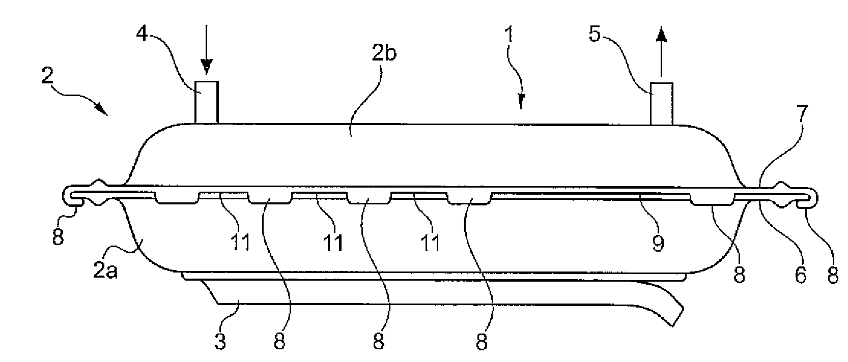
[0016]FIG. 1 shows a steam generator 1 comprising a disc-shaped container 2 and an electrical heating element 3 fixed to the outside of the container 2. The container 2 has an inlet 4 for water an outlet 5 for steam.

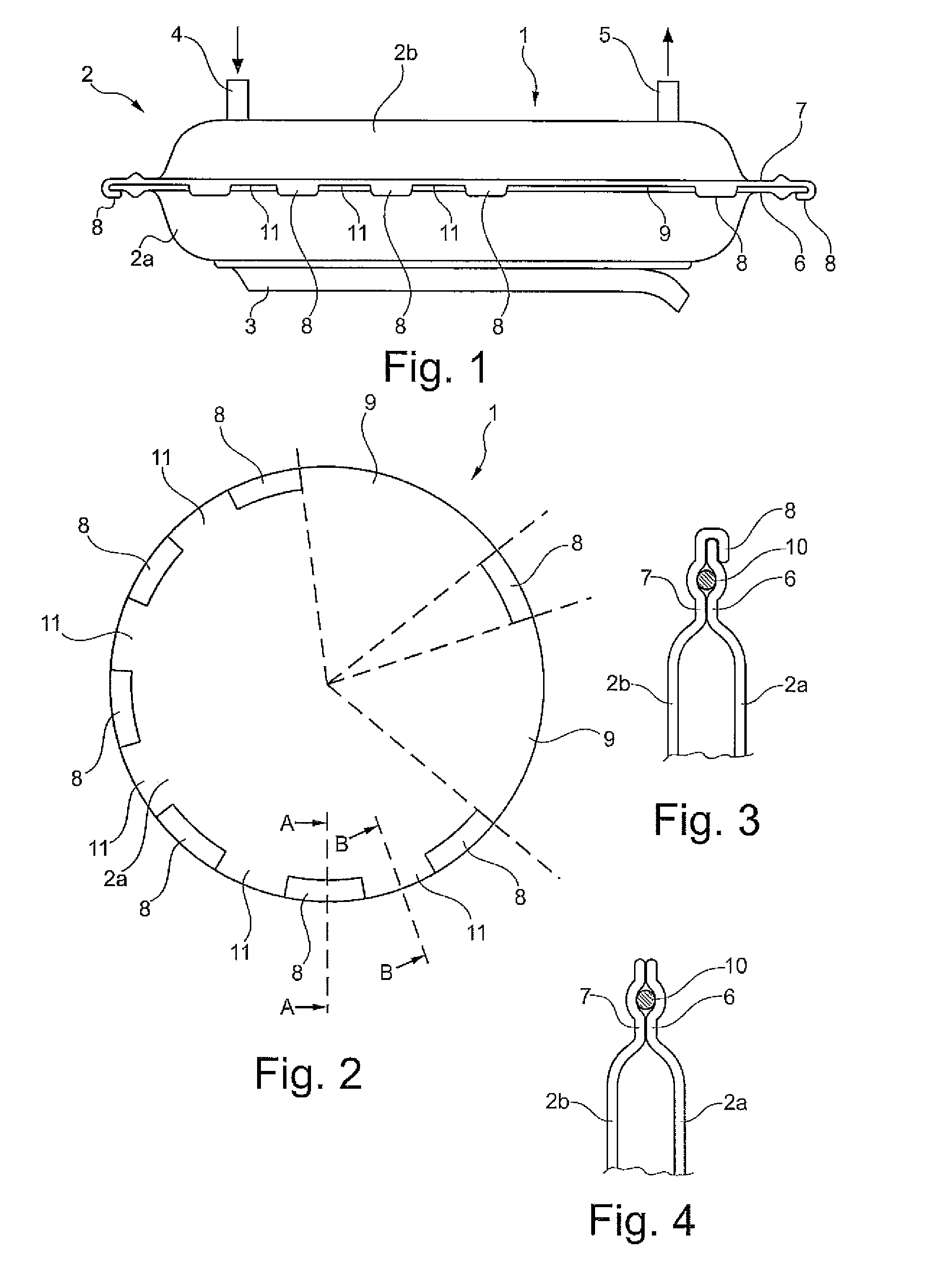
[0017]The container 2 comprises a bottom part 2a having a flange 6 and a lid part 2b resting against the flange 6 thereby covering the bottom part 2a. In the example shown these two container parts 2a, 2b are of substantially equal shape and the lid part 2b is also provided with a flange 7. Although in principle the lid part 2b might simply be a flat disc.

[0018]The two container parts 2a, 2b are fixed to each other by clamping. The clamping forces are caused by rim sections 8 of one of the container parts 2a, 2b which are folded over the rim of the other container part. In the example shown, rim sections 8 of the lid part 2b are folded over the rim of the bottom part 2a. Such rim sections 8 might just as well be provided on the bottom part 2a and folded over the rim of t...


PUM


Abstract

The invention refers to a steam generator for household appliances. The steam generator comprises a container having an inlet for water and an outlet for steam, and an electrical heating element fixed to the container. The container comprises a first part and a second part which are connected along a joint such that a critical pressure inside the container causes a slit to appear in a predefined section of the joint, said slit providing a security vent for releasing pressure.

Description

[0001]The invention refers to a steam generator for household appliances like washing machines, laundry driers, electric irons, espresso machines or ovens.[0002]Such steam generators have an inlet for water and an outlet for steam. If the outlet is clogged a continued steam generation might cause a dangerous increase of pressure and ultimately an explosion.[0003]A steam generator suitable for household appliances is disclosed in DE 10 2006 020 280 A1. The known device generates steam inside a container consisting of a bottom part and a lid part which are clamped together by a threaded bolt extending through the container. The bolt head presses against the outside of the bottom part; a nut screwed onto the bolt presses against the outside of the lid part. A joint between the bottom part and the lid part is sealed by an elastic adhesive. If the pressure inside the container increases beyond a certain level the adhesive will fail and pressure vented through a rupture along the joint.[0...

Claims


Application Information

Patent Timeline
Patent Type & Authority Applications(United States)
IPC IPC(8): F22B1/28
CPCF22B1/284
Inventor KLEEMANN, MARTINSCHULZE, MARC
Owner EICHENAUER HEIZELEMENTE
Why Eureka
Try Eureka