Method of fastening an edge structure to a construction element

a construction element and edge structure technology, applied in the direction of paper/cardboard containers, other plywood/veneer working apparatus, furniture parts, etc., can solve the problems of reducing the thickness tolerance of the lightweight building board, reducing the overall weight of the board, so as to achieve the effect of ensuring the thickness tolerance and avoiding the for

Active Publication Date: 2016-04-28
WOODWELDING
View PDF2 Cites 4 Cited by
  • Summary
  • Abstract
  • Description
  • Claims
  • Application Information

AI Technical Summary

Benefits of technology

[0018]Due to this approach of fastening the edge structure to the cover regions—and not primarily to the middle region, the energy impact is minimized and the achievable production speed is enhanced compared to approaches that comprise planar attaching of an edge structure. The enhanced stability of the cover regions is used, and due to the fastening to both cover regions, a dense and neat connection results.
[0022]The procedure according to the invention produces the important advantage that it allows the use of a relatively low-cost element—the edge structure—which can also be used with simple means—that is, for example, an ultrasonic device with a sonotrode. The ultrasonic device with the sonotrode may be a portable device (‘handheld device’) or a device similar to a fixedly installed drilling machine carried by a frame, with which it is possible to carry out not only the fastening of the edge support but also other working steps. The ultrasonic device may also be a customary stationary ultrasonic machine, as also known for industrial applications; the procedure according to the invention is also suitable for industrial application.
[0023]The procedure according to the invention also makes it possible that the filling in the region of the narrow side does not have to be cleared out—and is preferably used as such. Even if it comprises regions running between the cover regions in the final state, the edge structure requires little depth, and, given sufficiently flexible filling material, said material can be readily forced in.
[0024]Furthermore, the invention makes it possible that the cover regions do not have to be pretreated—for example by providing channels, grooves, etc.—i.e. the at least one edge structure may be fastened after the cutting-to-size operation, without method steps that are specifically designed for the edge structure, although such steps are not ruled out.
[0025]During the anchorage of the edge structure, a supporting force that is directed inward—that is to say toward the other cover region respectively—may be exerted on the cover region or the cover regions. Such a supporting force prevents the cover regions from coming apart when the supporting edges are introduced; this helps, inter alia, to maintain the thickness tolerances of the lightweight building board.

Problems solved by technology

However, finishing the edges in such a way as to obtain an attractive appearance has, to some extent, not yet been satisfactorily accomplished.
However, they contribute significantly to the overall weight of the board and can only be retrofitted with considerable effort.
The support edge technique is also quite laborious and necessitates the use of machines especially provided for the support edges.
For anything other than industrial production, their use entails disadvantages and is even virtually impossible.
Also for these materials, there exists the challenge of efficiently and reliably attaching an edge structure to the construction element.
Similar problems arise if a construction element does not have discrete, distinct layers (cover layers, filling layer) but is composed of a material composition having a continuous density profile, with denser outer regions and a less dense inner region.

Method used


Image

  • Method of fastening an edge structure to a construction element
  • Method of fastening an edge structure to a construction element
  • Method of fastening an edge structure to a construction element

Examples


Embodiment Construction

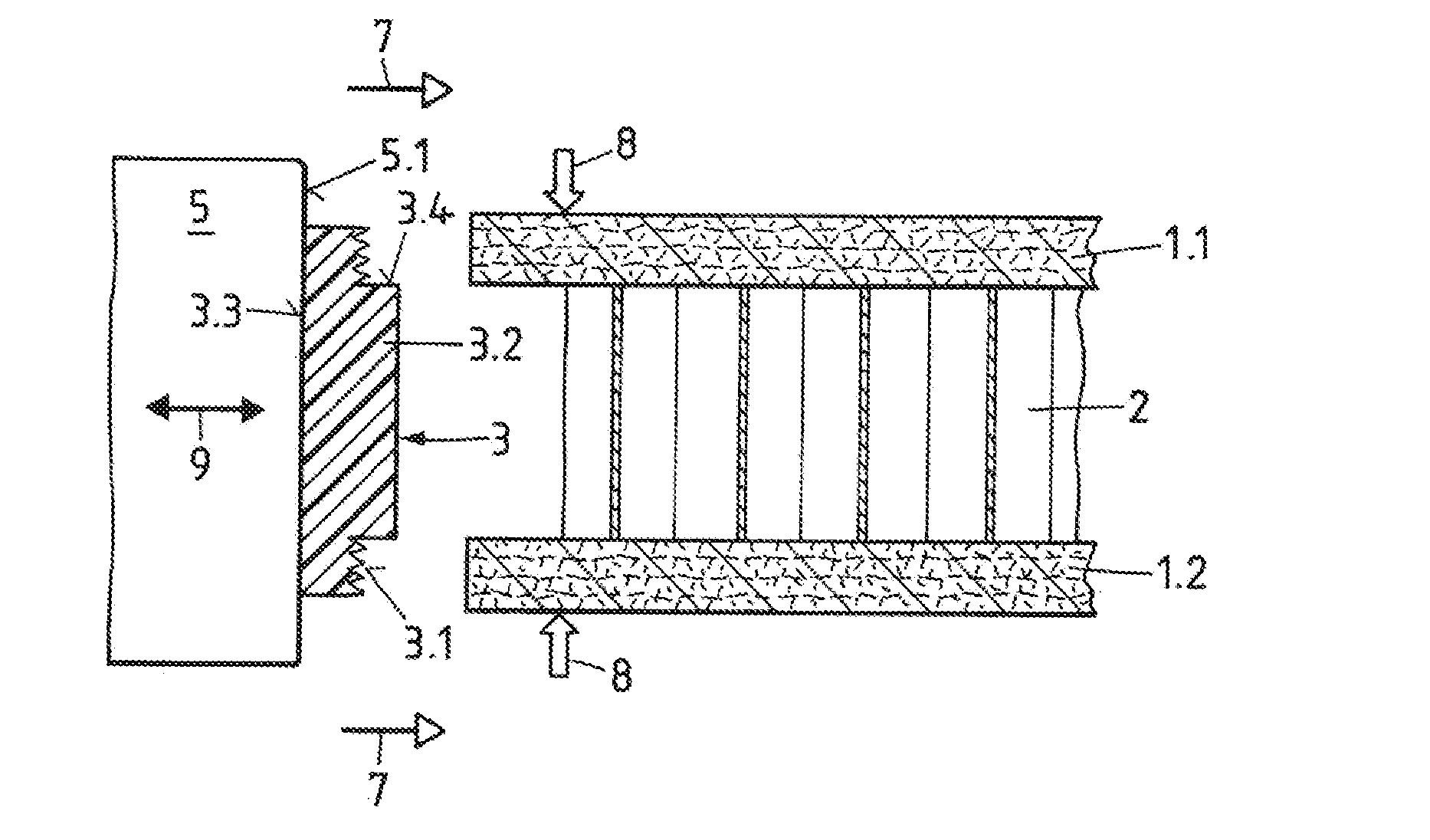
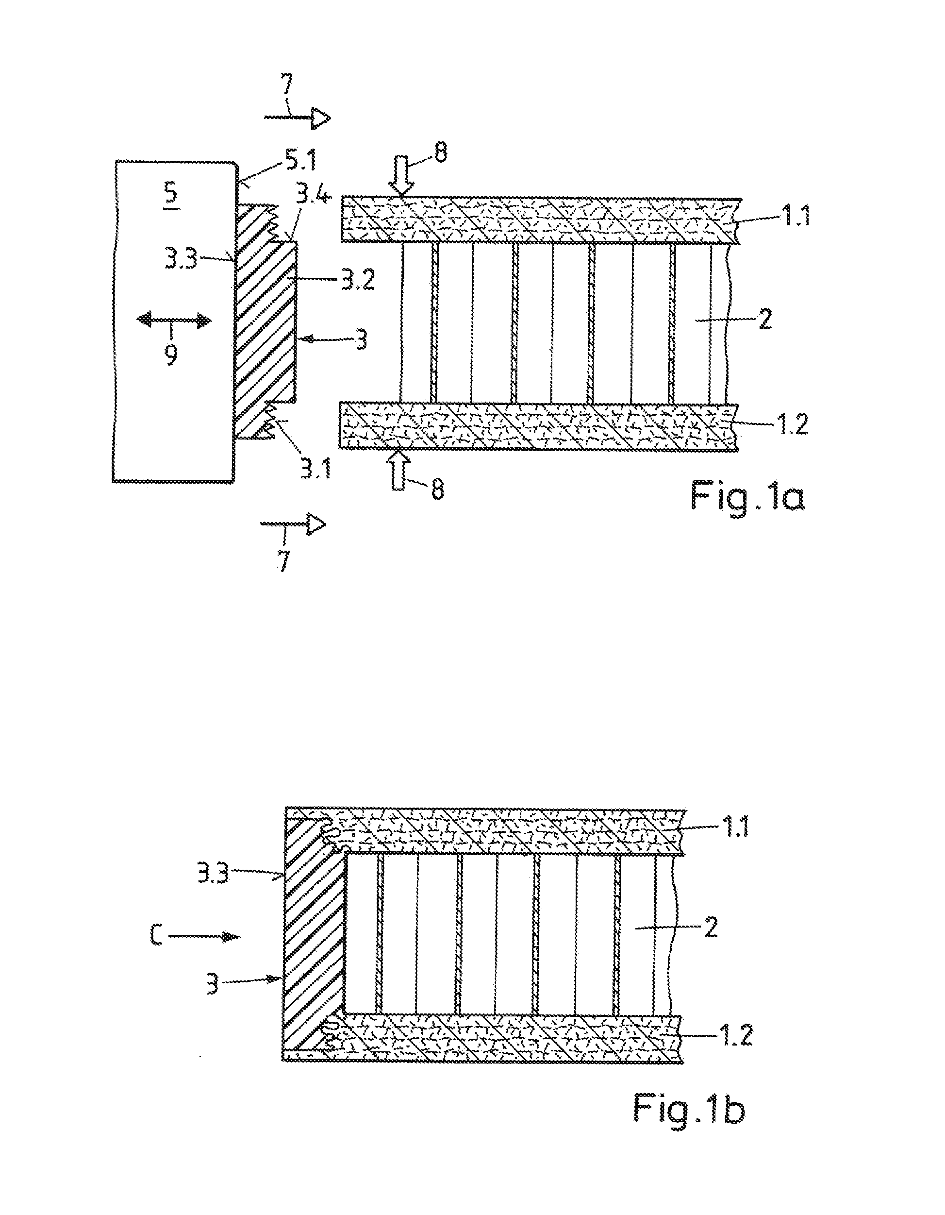
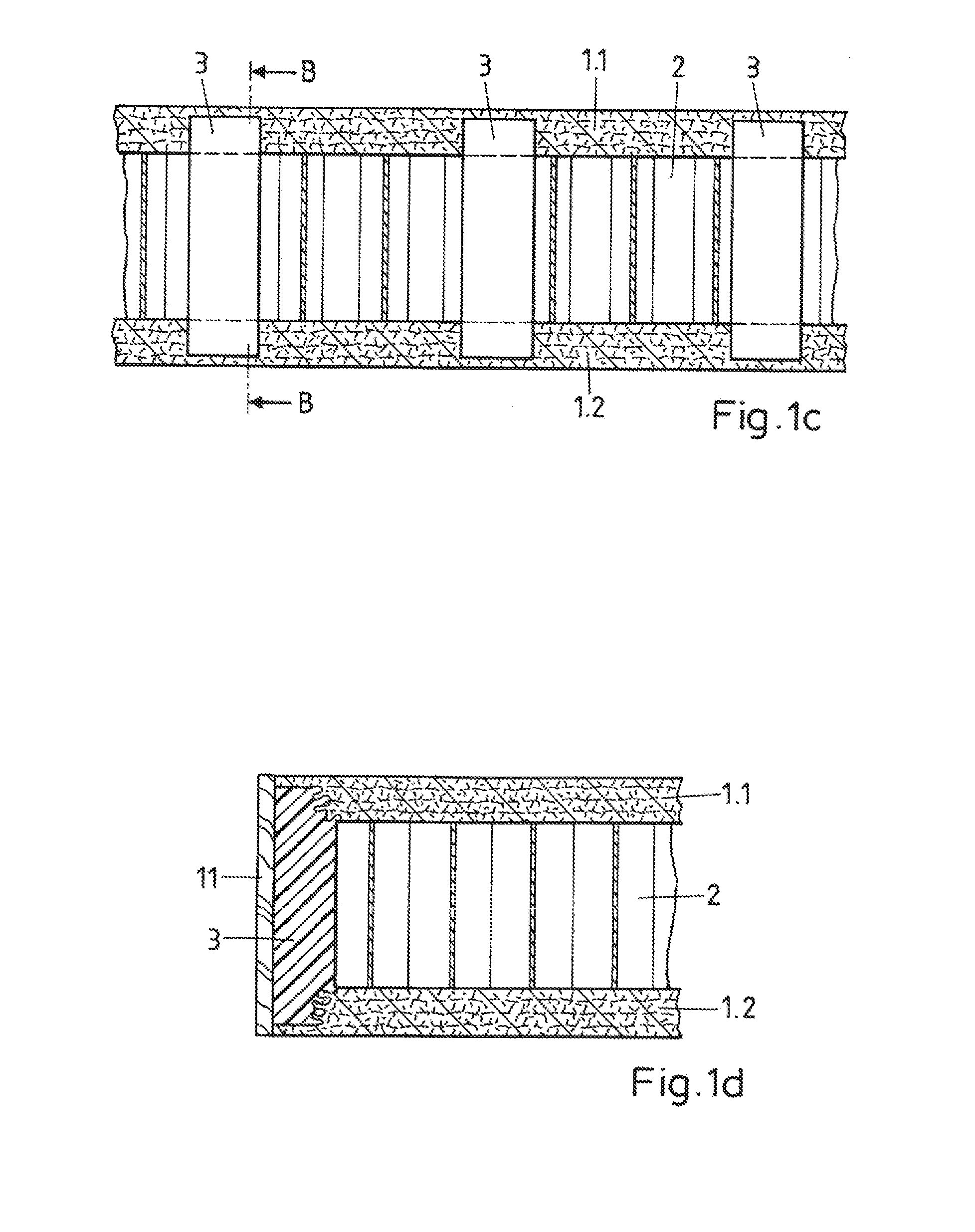
[0045]In the illustrative examples of FIGS. 1-8b, the construction element is a lightweight building board, and the edge structure is an edge support for fastening an edge, such as a decorative edge thereto.

[0046]The cut-to-size lightweight building board that can be seen in FIGS. 1a-1d comprises—as also in the embodiments described below—an upper cover layer 1.1 and a lower cover layer 1.2. The cover layers are produced from a derived timber material; for example, they are formed as particle boards, fiberboards or laminated (plywood) boards. The invention is also suitable, however, for the application where the cover layers are made of other materials, under some circumstances materials that are not wood-based, which have sufficient mechanical strength and dimensional stability and comprise structures that are suitable for interpenetration with liquefied thermoplastic material, for example plastic- or metal-based materials, in particular also composite materials.

[0047]The thickness...


PUM

PropertyMeasurementUnit
thicknessesaaaaaaaaaa

Abstract

A method of fastening an edge structure to a construction element includes providing the construction element, being a planar structure with with two cover regions and a middle region between the cover regions; providing the edge structure being continuously extended, the edge structure having contact surfaces with a thermoplastic material shaped to lie against the cover regions in an outer surface of the construction element, and, opposite the contact surfaces, a coupling-in surface for coupling energy into the edge structure; coupling energy into the edge structure and pressing the contact surfaces against the cover regions until at least a portion of the thermoplastic material is liquefied and pressed into the cover regions; and repeating or continuing the steps of coupling and pressing until the edge structure is attached to the building element at a plurality of discrete locations or over an extended region along an edge of the construction element.

Description

BACKGROUND OF THE INVENTION[0001]1. Field of the Invention[0002]The invention relates industrial fastening techniques such as used in construction, such as lightweight construction, machine construction, automotive and aircraft construction and furniture industry.[0003]2. Description of Related Art[0004]Lightweight building boards consist of two outer, relatively thin cover layers, for example particleboards, and a filling, for example a honeycomb structure made of card, arranged between the cover layers. Lightweight building boards of this type are mechanically very stable, lightweight, and can look attractive if the edges are finished neatly. Specifically because of their low weight and also because of the low consumption of resources in their production, they are becoming increasingly popular.[0005]Edges (decorative edges) for such lightweight building boards are, for example, plastic strips sealed on the outer surface and provided with a suitable decoration, and may furthermore ...

Claims


Application Information

Patent Timeline
Patent Type & Authority Applications(United States)
IPC IPC(8): B32B3/08B29C65/08
CPCB32B3/08B29C65/08B32B2479/00B32B2607/00B32B2605/00B29L2031/10B29K2707/04B29L2031/44B29K2311/12B27D5/003B29C65/645B29C66/3452B29C66/534B29C66/5346B29C66/71B29C66/7212B29C66/72525B29C66/73161B29C66/7392B29C66/7486B29C66/7487B29K2023/06B29C66/8322B29K2023/12B29K2027/06B29K2055/02B29K2069/00B29K2077/00B29K2311/14B29C63/0026B29K2101/12B29L2031/608B29K2709/08B29K2105/12Y10T428/239Y10T428/24008B29C66/30221B29C66/30223B29C66/112B29C66/114B29C66/1222B29C66/1224B29C66/126B29C66/21B29C66/30326B29C66/472B29C66/61B29K2307/04B29K2309/08B29K2067/00B29K2025/06B29K2033/12B29K2025/04B29C66/303B29C65/00B29C65/80
Inventor TORRIANI, LAURENTLEHMANN, MARIOAESCHLIMANN, MARCEL
Owner WOODWELDING
Why Eureka
Try Eureka