Electrophoretic displays containing magnetic particles

a technology of magnetic particles and display screens, applied in the field of electroctrophoretic displays, can solve the problems of preventing their widespread use, displaying more than two colors, and inadequate service life of these displays

Inactive Publication Date: 2005-03-22
E INK CORPORATION
View PDF110 Cites 542 Cited by
  • Summary
  • Abstract
  • Description
  • Claims
  • Application Information

AI Technical Summary

Benefits of technology

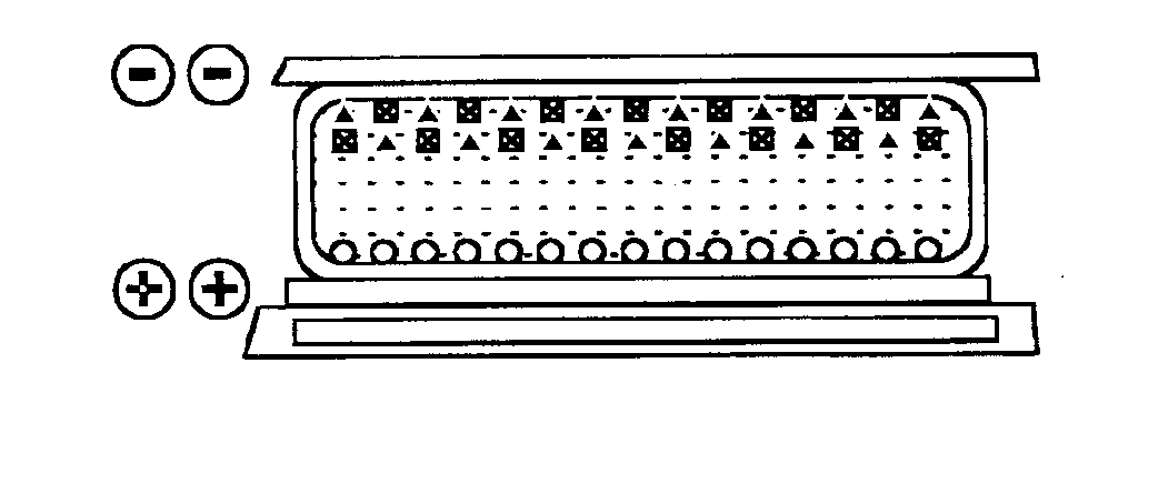
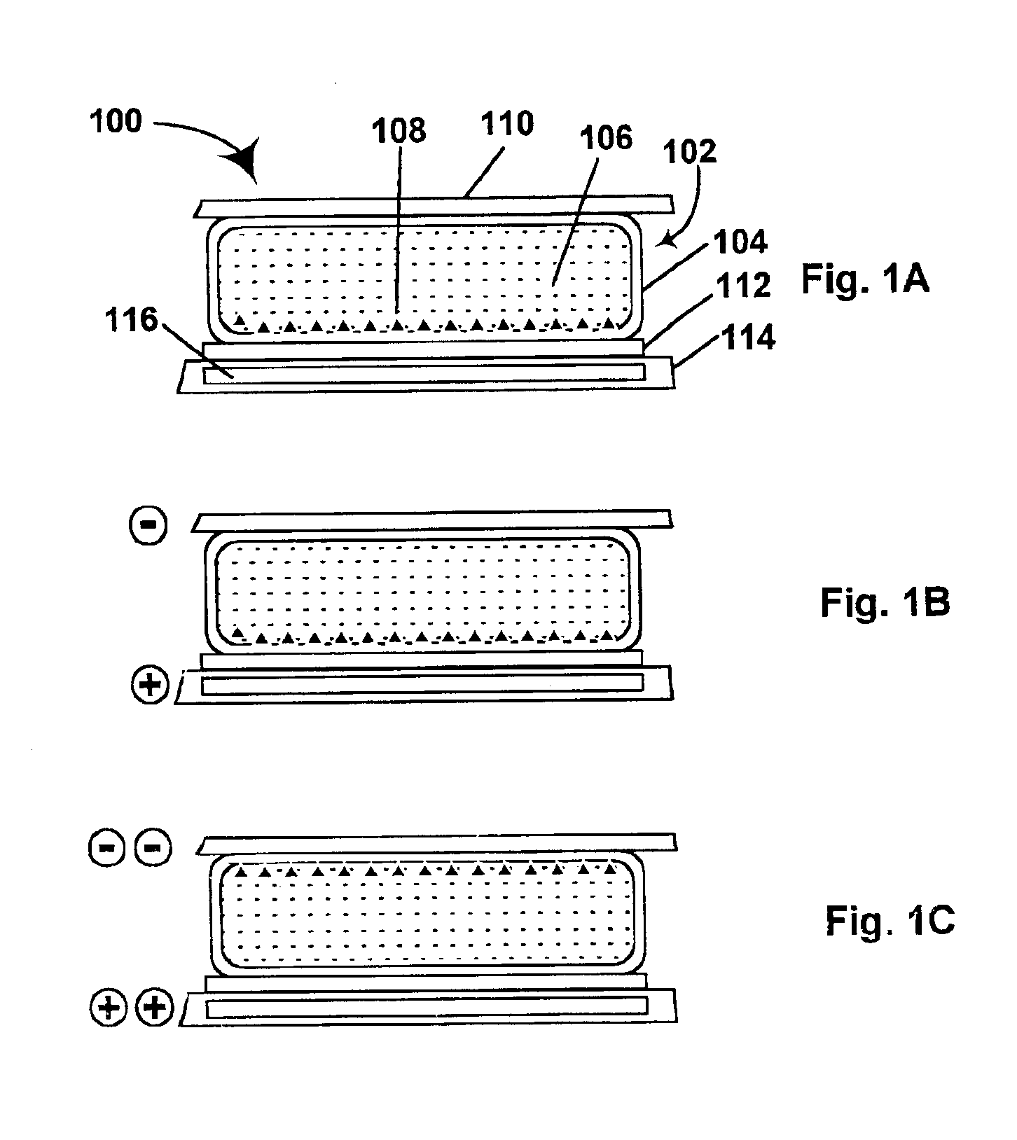
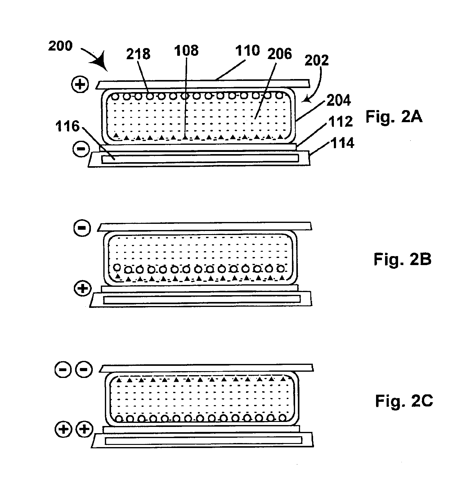
(c) applying to the medium an electric field having a polarity and magnitude sufficient to cause the particles to move through the suspending fluid against the magnetic forces applied to the particles by the magnet, thereby causing the particles to move adjacent the second surface of the medium and the second optical characteristic of the particles to be visible at the second surface.
Although other magnetic particles may be employed, the preferred magnetic material for use in the media and displays of the present invention is iron tetroxide (Fe3O4), usually known as “magnetite” or “lodestone”, the most common mineral forms of this material. This material is inexpensive and can readily be reduced to the particle size range (about 0.25 to 5 μm) required for use in electrophoretic displays. In all the embodiments of the present invention, it is preferred that at least the magnetic particles bear a polymer coating, this polymer coating preferably being formed by one of the processes described in copending Application Serial No. 60 / 291,061 filed May 15, 2001; the entire contents of this copending application are herein incorporated by reference. It has been found difficult to produce, in the hydrocarbon-based suspending fluids typically used in electrophoretic media, a dispersion of magnetite particles which is stable for a sufficiently long period to be commercially useful unless the magnetite is polymer coated. Indeed, it is preferred that all the particles in the present media bear polymer coatings produced as described in this copending application, since such coatings are useful in increasing the stability of electrophoretic media containing particles bearing charges of opposite polarity.

Problems solved by technology

Nevertheless, problems with the long-term image quality of these displays have prevented their widespread usage.
For example, particles that make up electrophoretic displays tend to settle, resulting in inadequate service-life for these displays.
One problem with existing electrophoretic displays, whether encapsulated or unencapsulated, is that they have essentially no threshold for switching, i.e., that even a small electric field applied for a long period will cause the display to switch between its optical states.
Another problem in most electrophoretic displays is that any individual pixel can only display two colors (the colors of the dye and the single particle in a single particle display, or the colors of the two different types of particles in a dual particle display) together with intermediate gray states between these two colors, and this inability to display more than two colors leads to difficulties in providing full color displays.
However, if each pixel is to display both pure black and pure white, color images can only be produced if each pixel is also capable of displaying a third color.
Alternatively, if the electrophoretic display is to be used to provide a full color RGB or CMY display (for example, as a substitute for a color liquid crystal display), the reflective nature of an electrophoretic display leads to problems in obtaining satisfactory color saturation.
While this type of display can give good results, in some cases it may be difficult to ensure that the three types of particles can retain substantially non-overlapping electrophoretic mobilities over a range of operating conditions, so that some muddying of the colors may result.

Method used


Image

  • Electrophoretic displays containing magnetic particles
  • Electrophoretic displays containing magnetic particles
  • Electrophoretic displays containing magnetic particles

Examples


example 1

This Example illustrates the provision of a silica coating on a magnetic particle which may be used in the present media and displays. The procedure used is adapted from U.S. Pat. No. 3,639,133.

Magnetite (Fe3O4, 50 g, ground to an average particle size of about 0.1 to 0.6 μm; the material used was Bayferrox 303T, available from Bayer AG, Leverkusen, Germany “BAYFERROX” is a Registered Trade Mark) was placed in a sodium silicate solution (415 ml of a 0.073M solution with 1.9% sodium hydroxide), and the resultant mixture was rapidly stirred in air and then sonicated at 30-35° C. The suspension was then heated to 90-95° C. over a period of 1 hour and sulfuric acid (150 ml of a 0.22 M solution) and additional sodium silicate (75 ml of a 0.83 M solution with 0.2% sodium hydroxide) were added simultaneously over a period of 2.5 to 3 hours, with stirring. After these additions had been completed, the reaction mixture was stirred for an additional 15 minutes, then cooled slowly to room temp...

example 2

This Example illustrates reaction of the silica-coated pigment prepared in Example 1 with a bifunctional reagent in the first stage of a process to provide a polymer-coated magnetite useful in the electrophoretic media and displays of the present invention.

To a mixture of ethanol (1000 ml) and water (100 mL), concentrated ammonium hydroxide was added until the pH reached 9.0-9.5, N-[3-(trimethoxysilyl)-(4-vinylbenzyl)ethylene diamine hydrochloride (40 g of a 40 weight per cent solution in methanol) was added, and the resultant solution was stirred rapidly for 4 minutes. The silica-coated magnetite (50 g) prepared in Example 1 was then added, and the mixture stirred rapidly for 7 minutes. The resultant suspension was poured into plastic bottles and centrifuged at 3500 rpm for 30 minutes. The supernatant liquor was decanted, and the silanized pigment re-dispersed in ethanol and centrifuged at 3500 rpm on the same centrifuge for 30 minutes, and the liquid decanted. The washing was repe...

example 3

This Example illustrates conversion of the silanized pigment produced in Example 2 to the corresponding polymer-coated magnetite.

The silanized pigment produced in Example 2 (50 g) was placed in a round-bottomed flask with toluene (50 g) and lauryl methacrylate (50 g). The resultant mixture was stirred rapidly under a nitrogen atmosphere (argon may alternatively be used) for 20 minutes, then slowly heated to 50° C. and AIBN (0.5 g in 10 ml of toluene) added quickly. The suspension was then heated to 65° C. and stirred at this temperature under nitrogen for a further 18 hours. The resultant viscous suspension was poured into plastic bottles, the flask being washed out with ethyl acetate to remove residual product and the ethyl acetate solution added to the bottles. The bottles were centrifuged at 3500 rpm for 30 minutes. The supernatant liquor was decanted, and the polymer-coated pigment re-dispersed in ethyl acetate and centrifuged at 3500 rpm for 30 minutes, and the liquid decanted....


PUM

PropertyMeasurementUnit
sizeaaaaaaaaaa
poling widthsaaaaaaaaaa
particle sizeaaaaaaaaaa

Abstract

An electrophoretic medium comprises a plurality of one or more types of particles suspended in a suspending fluid. The particles include at least one electrically charged, electrophoretically mobile particle capable of translating through the suspending fluid upon application of an electric field to the medium and at least one magnetic particle. A magnet is disposed adjacent the electrophoretic medium to introduce a threshold resistance to magnetic particle movement.

Description

BACKGROUND OF INVENTIONThis invention relates to electrophoretic displays containing magnetic (i.e., ferromagnetic or ferrimagnetic) particles, and to media for use in such displays. More specifically, this invention relates to such displays and media in which the magnetic particles are used either to provide a threshold for switching of the optical states of the displays and media, or to allow the displays and media to exhibit more than two colors at any one pixel.Electrophoretic displays have been the subject of intense research and development for a number of years. Such displays can have attributes of good brightness and contrast, wide viewing angles, optical state bistability, and low power consumption when compared with liquid crystal displays. (The terms “bistable” and “bistability” are used herein in their conventional meaning in the art to refer to displays comprising display elements having first and second display states differing in at least one optical property, and suc...

Claims


Application Information

Patent Timeline
Patent Type & Authority Patents(United States)
IPC IPC(8): G02F1/01G02F1/167G02F1/09G02F1/1675
CPCG02F1/167G02F2001/094G02F1/1675G02F1/094
Inventor PULLEN, ANTHONY EDWARDMORRISON, IAN D.PRATT, EMILY J.
Owner E INK CORPORATION
Why Eureka
Try Eureka