Optical system apparatus, camera and portable information terminal apparatus

a technology of optical system and image pickup, which is applied in the field of lens barrel, can solve the problems of affecting the operation of the lens barrel, affecting the operation of the camera, so as to reduce the dimensions of the image pickup apparatus and prevent rattling movemen

Inactive Publication Date: 2006-01-26
RICOH KK
View PDF2 Cites 30 Cited by
  • Summary
  • Abstract
  • Description
  • Claims
  • Application Information

AI Technical Summary

Benefits of technology

[0017] One aspect of the present invention, which has been made to solve the above problems, is to provide an optical system apparatus which is capable of easily reducing the dimension of a lens barrel in a direction of an optical axis when photographing is not carried out (when lenses are stored), the dimension of the lens barrel in a plane orthogonal to the optical axis, and consequently, to reduce the dimensions of an image pickup apparatus, and also to prevent a lens barrier covering a front side of the lenses from interfering with the collapsing type lens barrel when the lens barrel is collapsed to be stored and to prevent a rattling movement of the lens barrier.

Problems solved by technology

However, since a diameter of a lens arranged closest to a side of an object to be photographed is the largest in the photographing lens of a recent camera equipped with a wide-angle lens, the lens barrel becomes large when the lens barrel barrier is provided in the lens barrel in which the lens having the largest diameter is accommodated.
However, it is often the case that a rattling movement or an abnormal sound is produced when the user shakes the camera at the time that the camera is carried for example and is not used, due to the presence of the space.
As a result, a problem arises that the dimensions of the image pickup apparatus, in particular, the dimension as viewed from a front side of the image pickup apparatus increases.
Further, in the above structures disclosed in JP-A 2003-315861 and JP-A 2003-149723, the operations of the lens groups become complicated, inducing the lens barrier covering the front side of the lenses to easily interfere with the collapsing type lens barrel when the lens barrel shifts towards the collapsed and stored state.
Also, according to the structure disclosed in JP-A 2001-228507, there is a problem that its structure is difficult to be applied to the camera other than the manual open-close barrier type, since there is a variation in the engagement between the protrusion on the back surface of the external barrier and the protrusion on the front cover.
Therefore, there is also a problem in JP-A 2001-228507 that a cost of the entire camera increases since the processes for manufacturing the protrusions as components and attaching each of the protrusions to the back surface of the external barrier and front of the front cover increase.
According to the structure disclosed in JP-A 2001-290196, since the front cover of the camera body and the external barrier are always attached to each other, there is a problem that it is necessary to increase a driving force of an actuator in the automatic open-close barrier type in a case where the actuator is driven by the main switch to open and close the external barrier.
Thereby, a problem also arises in JP-A 2001-290196 that an operation of the camera including the external barrier tends to be uncertain and requires higher power consumption.
Furthermore, since JP-A 2001-91993 does not disclose measures for preventing the rattling movement between the front cover and the body barrier, the structure disclosed therein cannot solve the above-mentioned problems.

Method used


Image

  • Optical system apparatus, camera and portable information terminal apparatus
  • Optical system apparatus, camera and portable information terminal apparatus
  • Optical system apparatus, camera and portable information terminal apparatus

Examples


first embodiment

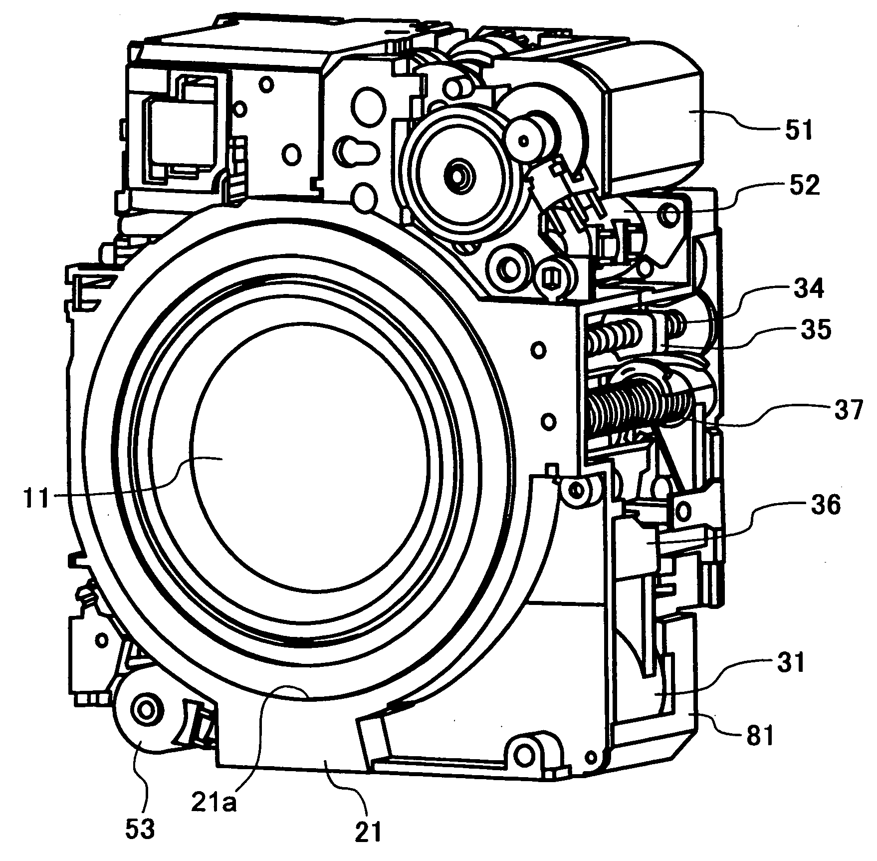
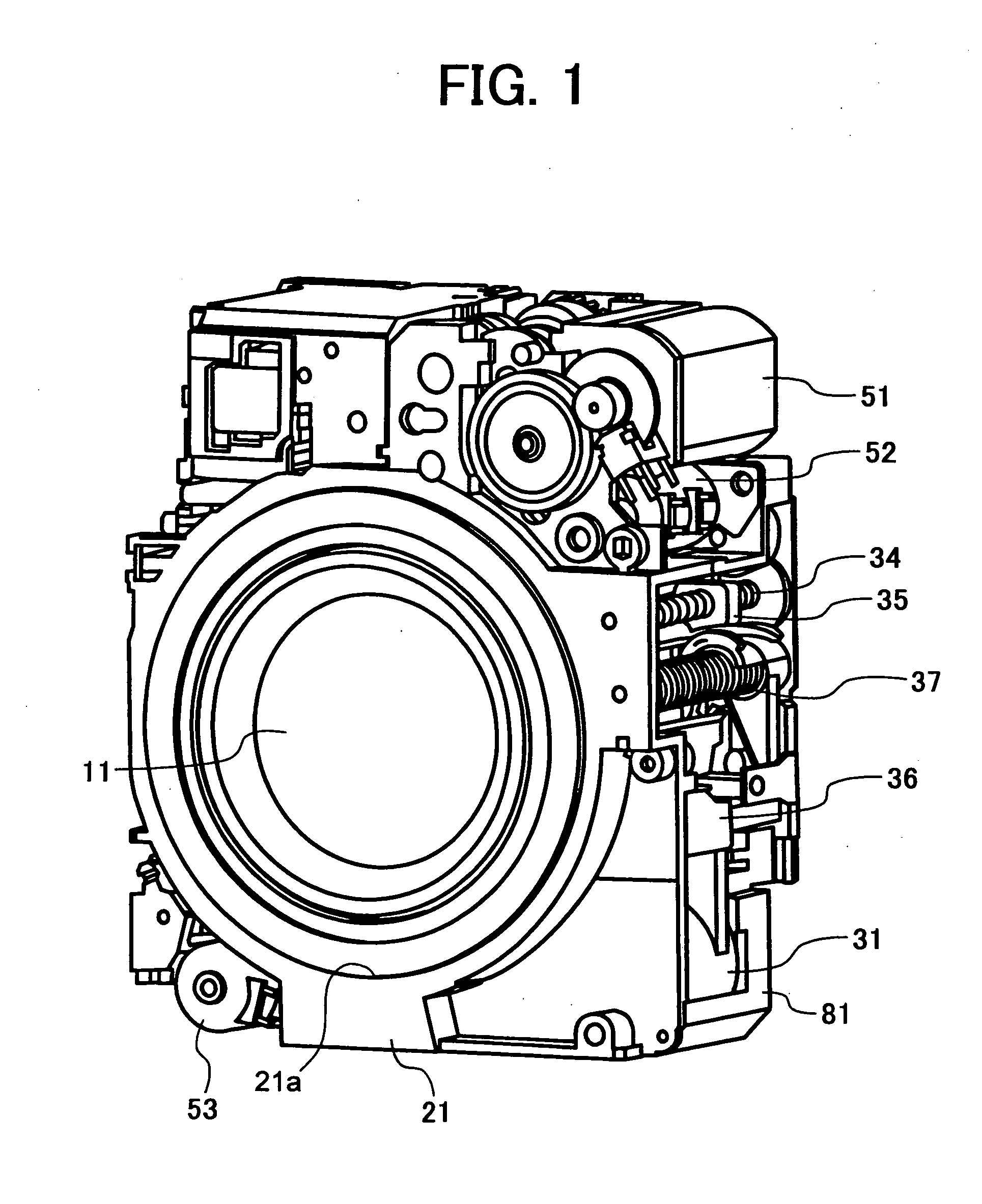
[0046]FIG. 1 to FIG. 16 show structures of portions of an optical system apparatus including a lens barrel according to a first embodiment of the present invention, and various operating states thereof.

[0047] As shown in FIG. 9, the optical system apparatus including the lens barrel according to the first embodiment of present invention includes a first lens group 11, a second lens group 12, a third lens group 13, a fourth lens group 14, a shutter / aperture unit 15, a solid-state image pickup device 16, a fixed frame 21, a fixed cylinder 21a, a first rotary cylinder 22, a first liner 23, a second rotary cylinder 24, a second liner 25, a cam cylinder 26, a lineally moving cylinder 27, and a third lens group frame 31. As to the third lens group 31, as shown in FIG. 2, FIG. 7, FIG. 8, and FIGS. 14 to 16, the optical system further includes a third lens group-main guide shaft 32, a third lens group-sub-guide shaft 33, a third lens group-lead screw 34, a female screw member 35, an impact...

second embodiment

[0077] Next, a second embodiment of the present invention, in which a camera is constructed by employing the optical system apparatus including the lens barrel according to the first embodiment of the present invention as a photographing optical system, will be explained in detail with reference to FIGS. 17A and 17B, and to FIG. 20.

[0078]FIGS. 17A and 17B are perspective views showing an exterior appearance and structure of the camera according to the second embodiment of the present invention as viewed from the object side, that is, from the front side which corresponds to the side of the photographing object. FIG. 17A shows a state in which a photographing lens is collapsed and stored in a body of the camera, and FIG. 17B shows a state in which the photographing lens is protruded from the camera body. FIG. 18 is a perspective view schematically showing the exterior appearance and structure of the camera as viewed from the photographer's side, that is, the back side of the camera....

third embodiment

[0088] Next, a third embodiment of the present invention, in which a camera is constructed by employing the optical system apparatus including the lens barrel according to the first embodiment of the present invention will be explained in detail with reference to FIG. 20 to FIG. 22.

[0089]FIG. 20 is an exploded perspective view of a structure of a lens barrel in a state in which the lens groups of the camera according to the third embodiment of the present invention are partly protruded and a structure of a front cover of the camera in a state in which a lens barrier is halfway closed, as viewed from the side of the image forming plane (from a back side). FIG. 21 is an exploded perspective view of the structures in the states shown in FIG. 20 as viewed from the object side (from a front side). FIG. 22 is a back view of the structure of the front cover of the camera from which an inner cover is removed, as viewed from the side of the image forming plane. In FIGS. 20 to 22, same refer...


PUM


Abstract

An optical system apparatus having a lens barrel, including multiple lenses, that is shifted between a stored position in which the lenses are collapsed and a photographing position in which the lenses are aligned along an optical axis of the apparatus. A lens barrier covers at least a front side of a lens. A barrier driving unit moves the lens barrier between a closed position and an opened position for retracting the lens barrier out of an operation space of the lens barrel. A barrier control member prevents the lens barrier from moving to the closed position from the opened position when the lens barrel is in the photographing position.

Description

CROSS-REFERENCE TO RELATED APPLICATIONS [0001] The present application claims the claims the benefit of priority to Japanese Patent Application No. 2004-217932, filed on Jul. 26, 2004, and Japanese Patent Application No. 2004-348005, filed on Dec. 1, 2004. In addition, the present application is related to the U.S. patent application entitled “Lens Barrel, Camera and Mobile Information Terminal” (Attorney Docket No. 274048US), which claims the benefit of priority to each of Japanese Patent Application 2004-217539, filed on Jul. 26, 2004; Japanese Patent Application 2005-044909, filed on Feb. 22, 2005; and Japanese Patent Application 2005-127226, filed on Apr. 25, 2005. In addition, the present application is related to the U.S. patent application entitled “Lens Barrel, Camera and Portable Information Terminal Device” (Attorney Docket No. 274053US), which claims the benefit of priority to Japanese patent application No. 2004-217924, filed on Jul. 26, 2004. In addition, the present ap...

Claims


Application Information

Patent Timeline
Patent Type & Authority Applications(United States)
IPC IPC(8): G03B17/04
CPCG03B17/04G02B7/102
Inventor NUNO, KATSUHIKOYAMANO, TOHRU
Owner RICOH KK
Why Eureka
Try Eureka