Polyaxial screw system and method having a hinged receiver

a polyaxial screw and receiver technology, applied in the field of polyaxial screw systems and methods comprising hinged receivers, can solve the problems of spinal rod threading and pseudoarthrosis

Inactive Publication Date: 2008-12-18
X SPINE SYST
View PDF78 Cites 146 Cited by
  • Summary
  • Abstract
  • Description
  • Claims
  • Application Information

AI Technical Summary

Benefits of technology

[0014]The present invention provides an improved fixation and locking system and method between an elongated member or rod and a screw that is screwed into bone.
[0016]Another object of the invention is to provide a simple locking connection between a screw and a socket of a receiver.
[0021]In another aspect, one embodiment comprises a bone fixation system comprising a receiver comprising a socket defining a socket area, the socket comprising at least one socket wall, the socket being adapted to receive a screw head of a polyaxial screw, a rod-receiving area defined by at least one rod-receiving wall, the rod-receiving area being adapted to receive a rod, and a pivot area between the rod-receiving area and the socket area, the pivot area permitting a dimension of the rod-receiving area to increase and substantially simultaneously being adapted to permit a dimension of the socket area to decrease so that the at least one socket wall may become locked to the screw head in response to movement of the at least one rod-receiving wall.

Problems solved by technology

However, in many cases, in particular cases involving fusion across the lumbosacral articulation and where there are many levels involved, pseudorarthrosis is a problem.
One detriment of the systems in the two Harms et al. patents is that the spinal rod must be threaded in order to accept the compression nuts.

Method used


Image

  • Polyaxial screw system and method having a hinged receiver
  • Polyaxial screw system and method having a hinged receiver
  • Polyaxial screw system and method having a hinged receiver

Examples


Embodiment Construction

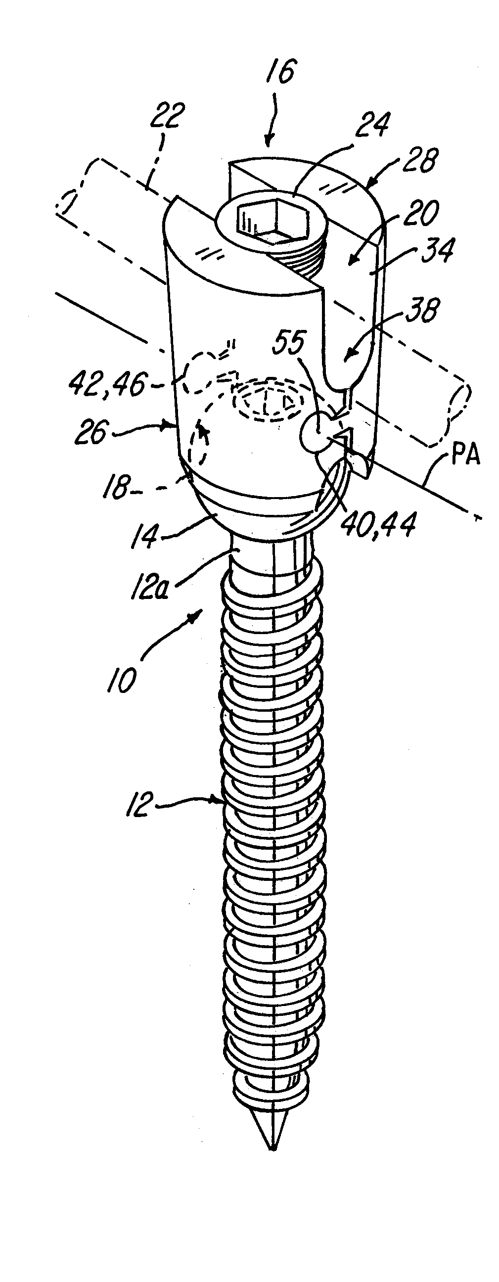
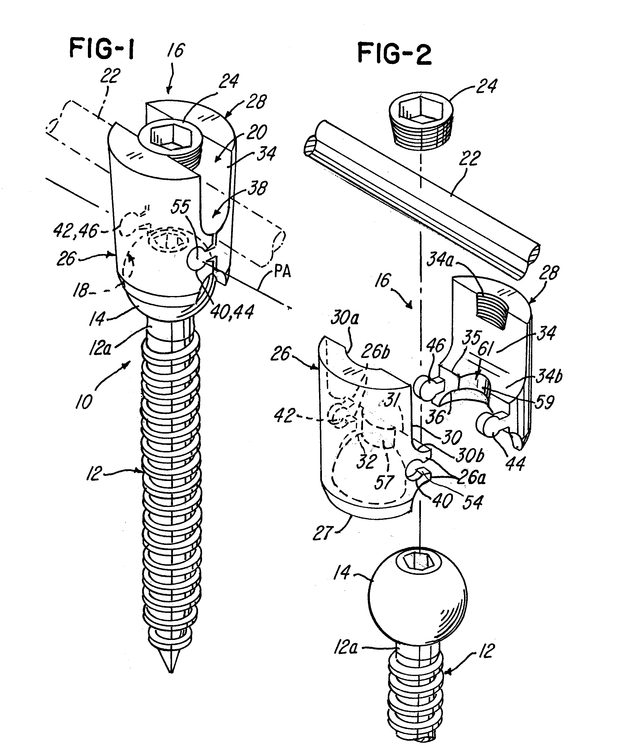
[0080]Referring now to FIG. 1, a polyaxial screw system 10 is shown comprising a screw 12 having a polyaxial screw head 14. The polyaxial screw system 10 further comprises a receiver 16 adapted to comprise or define a socket area 18 (FIG. 4) for receiving the polyaxial screw head 14 of the screw 12. The receiver 16 is further adapted to comprise or define a rod-receiving area 20 for receiving a rod 22 as illustrated in FIGS. 1-12.

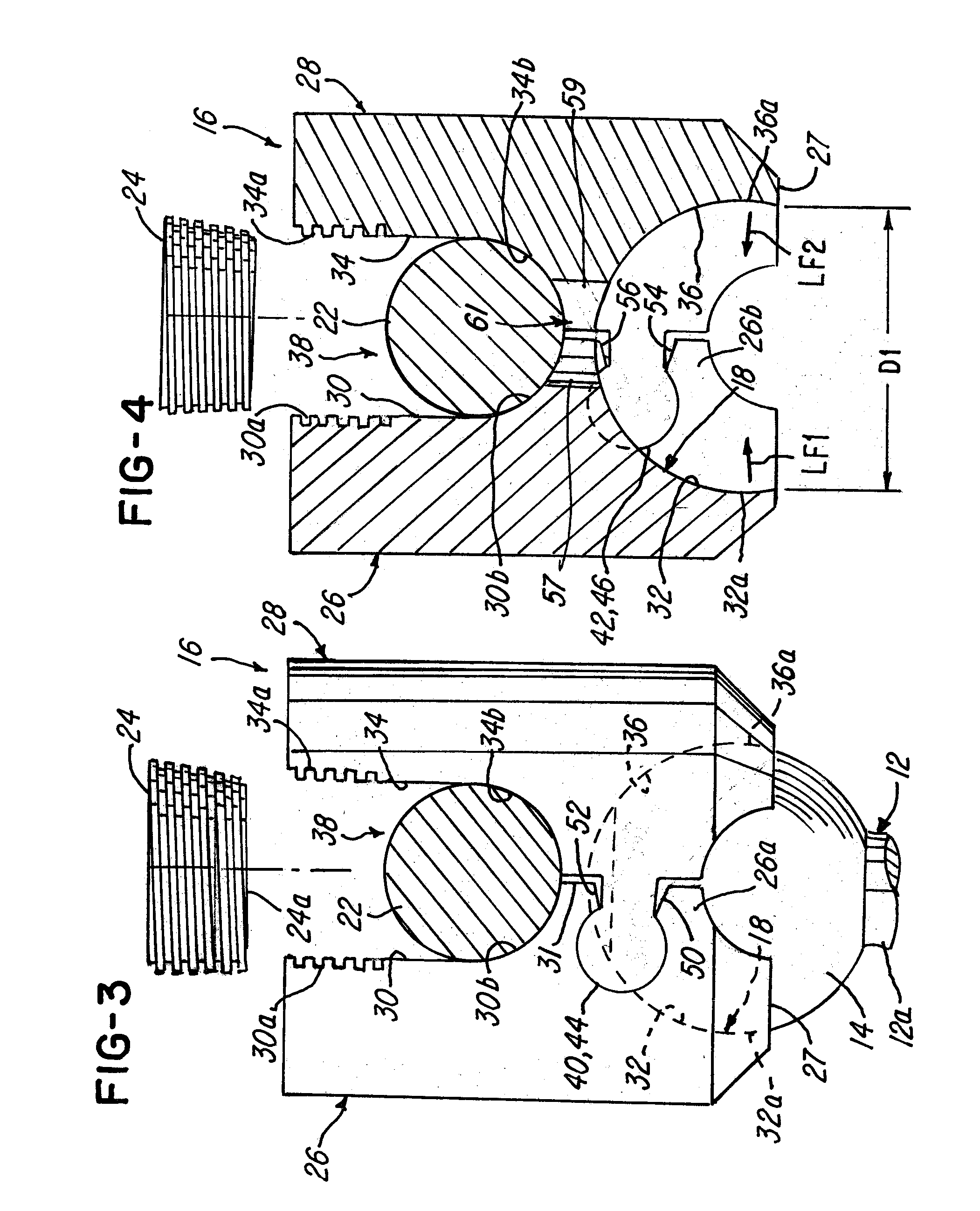
[0081]The receiver 16 in this embodiment comprises a first receiver member 26 and a second receiver member 28. As illustrated in FIGS. 3 and 4, the first receiver member 26 comprises a first rod-receiving wall 30 and a first socket wall 32 and an intermediate area 31 between the walls 30 and 32. The second receiver member 28 comprises a second rod-receiving wall 34 and a second socket wall 36 and a second intermediate area 35 between the walls 34 and 36. The first and second receiver members 26 and 28 are pivotally coupled at the intermediate areas 31 and 3...


PUM


Abstract

A polyaxial screw system and method are provided. The system comprises a receiver having a pivot area defined by a pivot joint or a material between a pair of receiver walls or members that permit the receiver walls or members to move or pivot relative to each other so that a dimension of a socket area can be changed. The socket area is defined by socket walls that when at least one of the receiver members pivots relative to another receiver member or wall, a distance between the socket walls gets smaller so that the socket walls can engage and lock against a head of a polyaxial screw.

Description

BACKGROUND OF THE INVENTION[0001]1. Field of the Invention[0002]This invention relates to a polyaxial screw system and method comprising a hinged receiver.[0003]2. Description of the Related Art[0004]Various methods of spinal immobilization have been known and used in the past. The preferred treatment for spinal stabilization is immobilization of the joint by surgical fusion or anthrodesis. This method has been known since development in 1911 by Hibbs and Albe. However, in many cases, in particular cases involving fusion across the lumbosacral articulation and where there are many levels involved, pseudorarthrosis is a problem. It was discovered that immediate immobilization was necessary in order to allow a bony union to form. Post operative external immobilization, such as the use of splints and casts, was a favored method of treatment, however, as surgical techniques have become more sophisticated, various methods of internal and external fixation have been developed.[0005]Intern...

Claims


Application Information

Patent Timeline
Patent Type & Authority Applications(United States)
IPC IPC(8): A61B17/04A61B17/70
CPCA61B17/7032A61B17/7037
Inventor KIRSCHMAN, DAVID LOUISHEMMELGARN, BRIAN J.
Owner X SPINE SYST
Why Eureka
Try Eureka