
Tissue extraction devices and methods

a tissue extraction and tissue technology, applied in the field of tissue extraction devices and methods, can solve problems such as large diameter, and achieve the effect of rapid liquid vaporization

Active Publication Date: 2012-12-27
MINERVA SURGICAL
View PDF13 Cites 142 Cited by
  • Summary
  • Abstract
  • Description
  • Claims
  • Application Information

AI Technical Summary

Benefits of technology

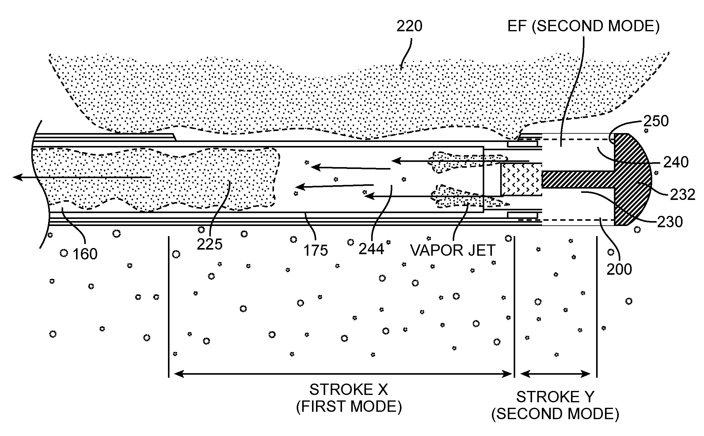
[0006]The present invention provides methods for resecting and removing target tissue from a patient's body, such as fibroids from a uterus. The tissue is cut, captured in a probe, catheter, or other tissue-removal device, and expelled from the capture device by vaporizing a fluid, typically a liquid, adjacent to the captured tissue in order to propel the tissue from the device, typically through an extraction or other lumen present in a body or shaft of the device. Exemplary embodiments, the tissue removal device comprise a reciprocating blade, tubular cutter, or the like, where the blade may be advanced past a cutting window on the device in order to sever a tissue strip and capture the strip within an interior volume or receptacle on the device. The liquid or other expandable fluid is also present in the device, and energy is applied to the fluid in order to cause rapid expansion, e.g. vaporization, in order to propel the severed tissue strip through the extraction lumen. In this way, the dimensions of the extraction lumen can be reduced, particularly in the distal regions of the device where size is of critical importance.
[0009]The tissue may be captured in a variety of ways. For example, the tissue may be resected with a blade number or alternatively with an RF electrode. In either case, the resected tissue may then be captured or sequestered within an interior passageway within the blade itself and / or within another portion of the probe. In addition to the propulsion force caused by the vaporizing fluid, the present invention might also rely on applying a negative pressure to a proximal end of the anterior passageway to assist in drawing the tissue in a proximal direction from the extraction lumen.
[0010]In a further method according to the present invention, tissue is removed from the interior of a patient's body by engaging a tubular cutter against the targeted tissue. An RF electrode arrangement on the cutter is energized to electrosurgically cut the tissue, and the same or a different RF electrode is used to vaporize a liquid to apply a positive fluid pressure to a distal surface of the cut tissue. Usually, the same RF electrode arrangement is used to both electrosurgically cut the tissue and to vaporize the liquid. In such instances, the cutter carrying the RF electrode is usually first advanced to electrosurgically cut the tissue and thereafter advanced into the liquid to vaporize the liquid. The liquid is usually present in a chamber or other space having an active electrode at a distal end thereof, and the RF electrode arrangement on the cutter comprises a return electrode. In this way, with the smaller active electrode on the distal side of the tissue, the energy which vaporizes the liquid will be concentrated in the chamber on the distal side of the tissue, thus causing rapid vaporization of the liquid and propulsion of the tissue through the extraction lumen.
[0012]In a still further method according to the present invention, tissue is cut and extracted by first cutting the tissue with a reciprocating cutting member over an extending stroke and a retracting stroke within a sleeve. The extending stroke cuts and captures tissue which has been drawn through a tissue-receiving window in the sleeve. Vaporization of a liquid distal to the captured tissue is caused by the cutting member while the cutting member is in a transition range between extension and retraction. The tissue is typically captured in the tissue extraction lumen formed at least partially in the cutter member. The cutter member typically carries a cutting electrode, and a second electrode is typically disposed at a distal end of the sleeve. Thus, RF current may be delivered to the cutting electrode and the second electrode in order to both effect cutting of the tissue over the extending stroke of the cutter and to also effect vaporization of the fluid while the cutter is in the transition range.

Problems solved by technology

While hysteroscopic resection can be effective in removing uterine fibroids, many commercially available instrument are too large in diameter and thus require anesthesia in an operating room environment.

Method used


Image

  • Tissue extraction devices and methods
  • Tissue extraction devices and methods
  • Tissue extraction devices and methods

Examples


Embodiment Construction

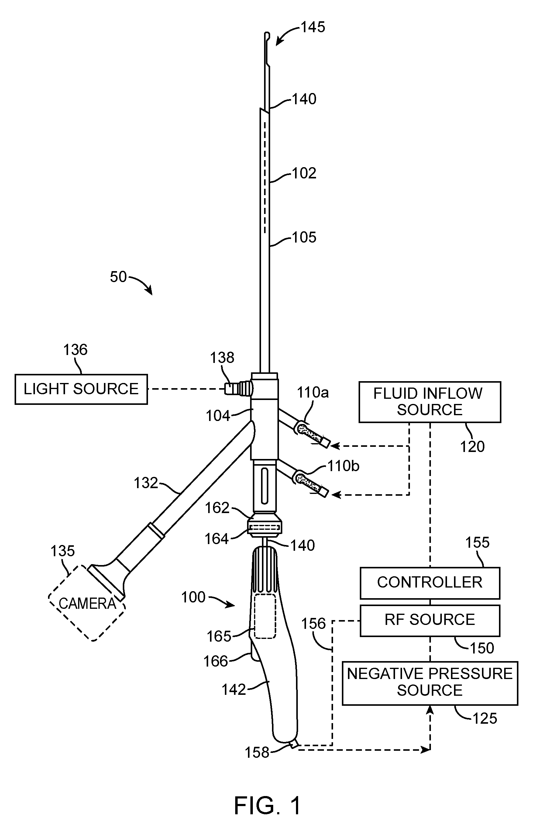
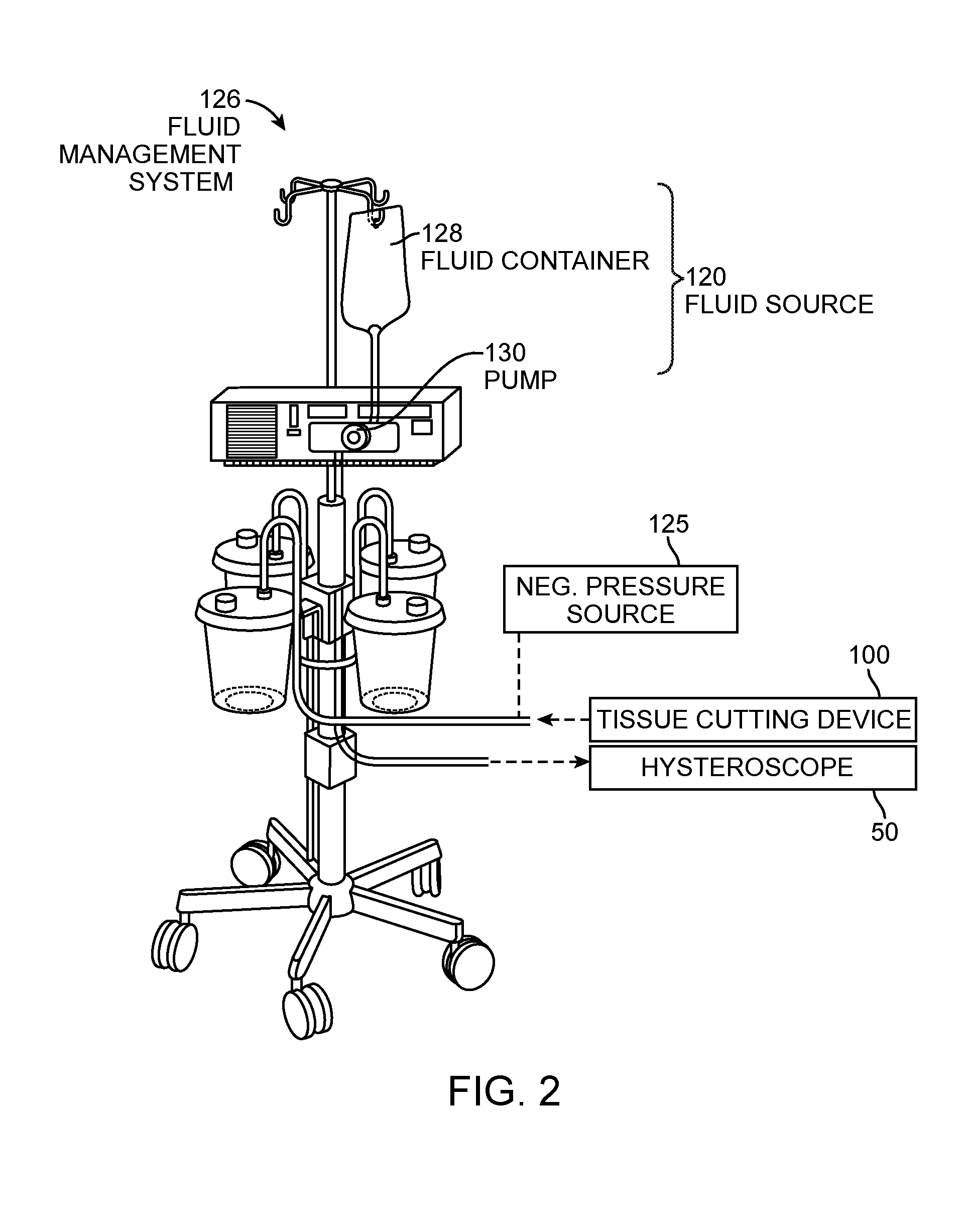
[0049]FIG. 1 illustrates an assembly that comprises an endoscope 50 used for hysteroscopy together with a tissue-extraction device 100 extending through a working channel 102 of the endoscope. The endoscope or hysteroscope 50 has a handle 104 coupled to an elongated shaft 105 having a diameter of 5 mm to 7 mm. The working channel 102 therein may be round, D-shaped or any other suitable shape. The endoscope shaft 105 is further configured with an optics channel 106 and one or more fluid inflow / outflow channels 108a, 108b (FIG. 3) that communicate with valve-connectors 110a, 110b configured for coupling to a fluid inflow source 120 thereto, or optionally a negative pressure source 125 (FIGS. 1-2). The fluid inflow source 120 is a component of a fluid management system 126 as is known in the art (FIG. 2) which comprises a fluid container 128 and pump mechanism 130 which pumps fluid through the hysteroscope 50 into the uterine cavity. As can be seen in FIG. 2, the fluid management syste...


PUM


Abstract

Tissue may be cut and extracted from an interior location in a patient's body using a probe or tool which both effects cutting and causes vaporization of a liquid or other fluid to propel the cut tissue through an extraction lumen of the cutting device. The cutting may be achieved using an electrosurgical electrode assembly, including a first electrode on a cutting member and a second electrode within a cutting probe or tool. Thus, over a first cutting portion, radio frequency current may help cut the tissue and over a second or over transition region, the RF current may initiate vaporization of the fluid or other liquid to propel the tissue from the cutting device.

Description

CROSS-REFERENCE TO RELATED APPLICATIONS[0001]This application claims the benefit of U.S. Provisional Application No. 61 / 501,106 (Attorney Docket No. 33291-712.101), filed on Jun. 24, 2011 and of U.S. Provisional Application No. 61 / 531,985 (Attorney Docket No. 33291-721.101), filed on Sep. 7, 2011, the full disclosures of which are incorporated herein by reference.FIELD OF THE INVENTION[0002]The present invention relates systems and methods for the cutting and extraction of uterine fibroid tissue, polyps and other abnormal uterine tissue.BACKGROUND OF THE INVENTION[0003]Uterine fibroids are non-cancerous tumors that develop in the wall of uterus. Such fibroids occur in a large percentage of the female population, with some studies indicating that up to 40 percent of all women have fibroids. Uterine fibroids can grow over time to be several centimeters in diameter and symptoms can include menorrhagia, reproductive dysfunction, pelvic pressure and pain.[0004]One current treatment of fi...

Claims


Application Information

Patent Timeline
Patent Type & Authority Applications(United States)
IPC IPC(8): A61B17/3205A61B18/14A61B18/08A61B18/18A61B18/20
CPCA61B18/18A61B18/1482A61B2018/00196A61B2018/00202A61B2018/00589A61B2018/00601A61B18/00A61B2018/048A61B2218/007A61B17/32002A61B2017/320028A61B17/3205A61B2018/00625A61B1/015A61B1/05A61B18/1206A61B2018/00559A61B2018/126A61B2018/1437A61B2218/002
Inventor SHADDUCK, JOHN H.GERMAIN, AARONKLEIN, KYLEWALKER, MICHAEL D.TRUCKAI, CSABA
Owner MINERVA SURGICAL
Learn More