Stent with enhanced crossability

Inactive Publication Date: 2006-04-18
CARDINAL HEALTH SWITZERLAND 515 GMBH
View PDF137 Cites 145 Cited by
  • Summary
  • Abstract
  • Description
  • Claims
  • Application Information

AI Technical Summary

Benefits of technology

[0012]The present invention is generally directed to the arrangement of the flexible connectors of a stent. The present invention further

Problems solved by technology

Atherosclerosis is the build-up of fatty deposits or plaque on the inner walls of a patient's arteries; these lesions decrease the effective size of the artery lumen and limit blood flow through the artery, prospectively causing a myocardial infarction or heart attack if the lesions occur in coronary arteries that supply oxygenated blood to the heart muscles.
This device is formed of multiple parts and is not continuously flexible along the longitudinal axis.
These designs have at least one

Method used


Image

  • Stent with enhanced crossability
  • Stent with enhanced crossability
  • Stent with enhanced crossability

Examples


Example

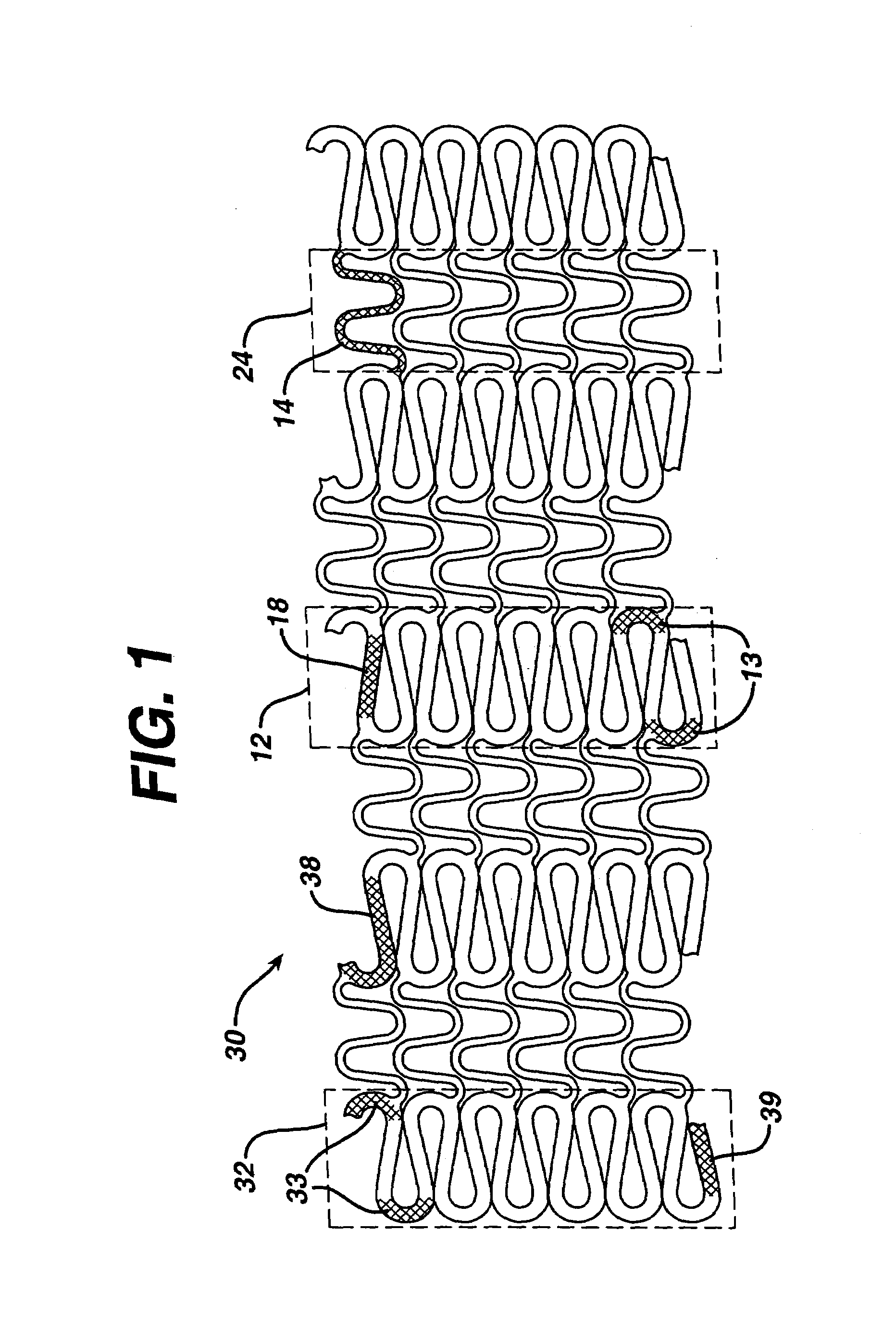
[0017]Briefly, FIG. 1 is a flat layout of a prior art stent, described by Fischell et al in U.S. Pat. No. 6,190,403, having a uniform strut width for the circumferential sets of strut members.

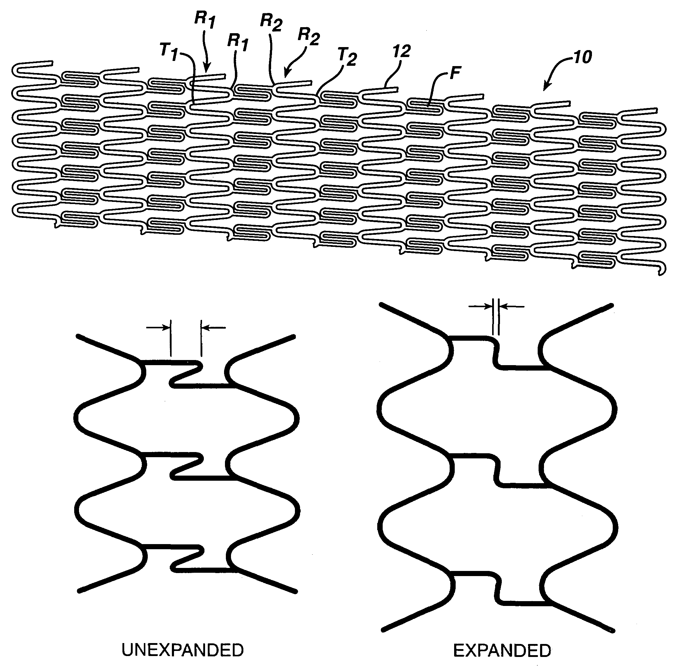
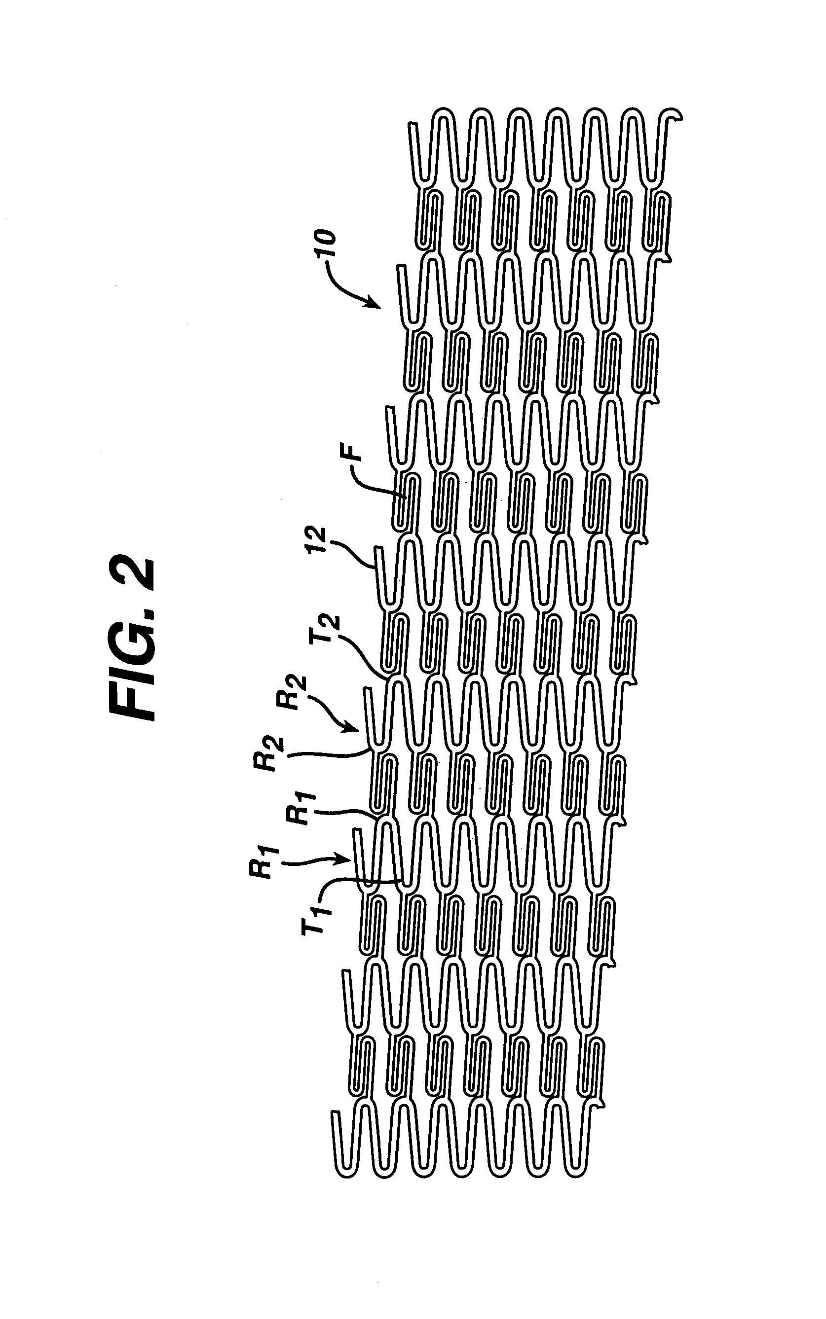
[0018]FIG. 2. is a flat layout of the stent of the invention, illustrating the radial strut 12 (along the longitudinal axis) and the flexible strut F (along the longitudinal axis). In this embodiment, adjacent rings of radial struts R1, R2 comprise periodic structures which are out-of-phase, meaning that peaks P1 in one ring R1 face peaks P2 in the adjacent ring R2 and that troughs T1 in one Ring R1 face troughs T2 in the adjacent ring R2. In the depicted embodiment, flexible struts link adjacent peaks P of the periodic structure of radial struts R. (In a different embodiment, flexible struts can link non-adjacent peaks.) In other embodiments of the present invention, adjacent rings of radial struts comprise periodic structures which are in-phase, meaning that peaks in one ring face troughs in ...


PUM


Abstract

A stent design is disclosed which has a flexible connector which has flexible arcs and flexible struts aligned similarly to the radial arcs and radial struts, such that the alignment of the flexible connector within the stent decreases the likelihood of the stent's catching on a non-smooth surface.

Description

FIELD OF THE INVENTION[0001]The present invention generally relates to implantable intraluminal medical devices, particularly stents. The present invention relates to an implantable intraluminal device which is useful for repairing or serving as a conduit for vessels narrowed or occluded by disease or for use in other body passageways requiring reinforcement or the like. More specifically, the present invention discloses an alignment of a flexible connector within a stent which decreases the likelihood of the stent's catching on a non-smooth surface.BACKGROUND OF THE INVENTION[0002]As background to a discussion of stents, one notes that in the 1970s, the technique of percutaneous transluminal coronary angioplasty (PTCA) was developed for the treatment of atherosclerosis. Atherosclerosis is the build-up of fatty deposits or plaque on the inner walls of a patient's arteries; these lesions decrease the effective size of the artery lumen and limit blood flow through the artery, prospect...

Claims


Application Information

Patent Timeline
IPC IPC(8): A61F2/06A61F2/90
CPCA61F2/91A61F2/915A61F2230/0054A61F2002/91558A61F2002/91583A61F2002/91533
Inventor MAJERCAK, DAVID C.HOJEIBANE, HIKMAT
Owner CARDINAL HEALTH SWITZERLAND 515 GMBH
Why Eureka
Try Eureka