
On-vehicle display apparatus

a technology for displaying equipment and vehicles, which is applied in the direction of television systems, electrical equipment casings/cabinets/drawers, instruments, etc., can solve the problems of damage, excessive force on the power transmission mechanism of the on-vehicle display apparatus, and difficulty in reducing the size and thickness of the apparatus, so as to achieve smooth movement, damage to the power transmission mechanism, and easy reduction in thickness

Active Publication Date: 2012-10-18
ALPINE ELECTRONICS INC
View PDF6 Cites 30 Cited by
  • Summary
  • Abstract
  • Description
  • Claims
  • Application Information

AI Technical Summary

Benefits of technology

[0011]It is an object of the present invention to provide an on-vehicle display apparatus that can be easily reduced in thickness and can prevent damage when an unwanted external force is applied to a display main body.
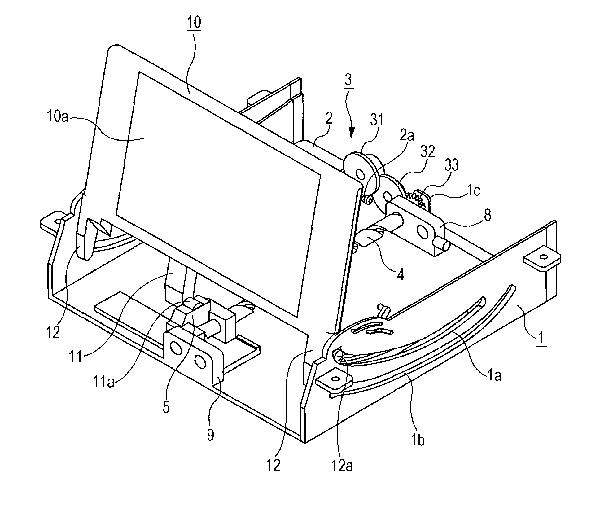
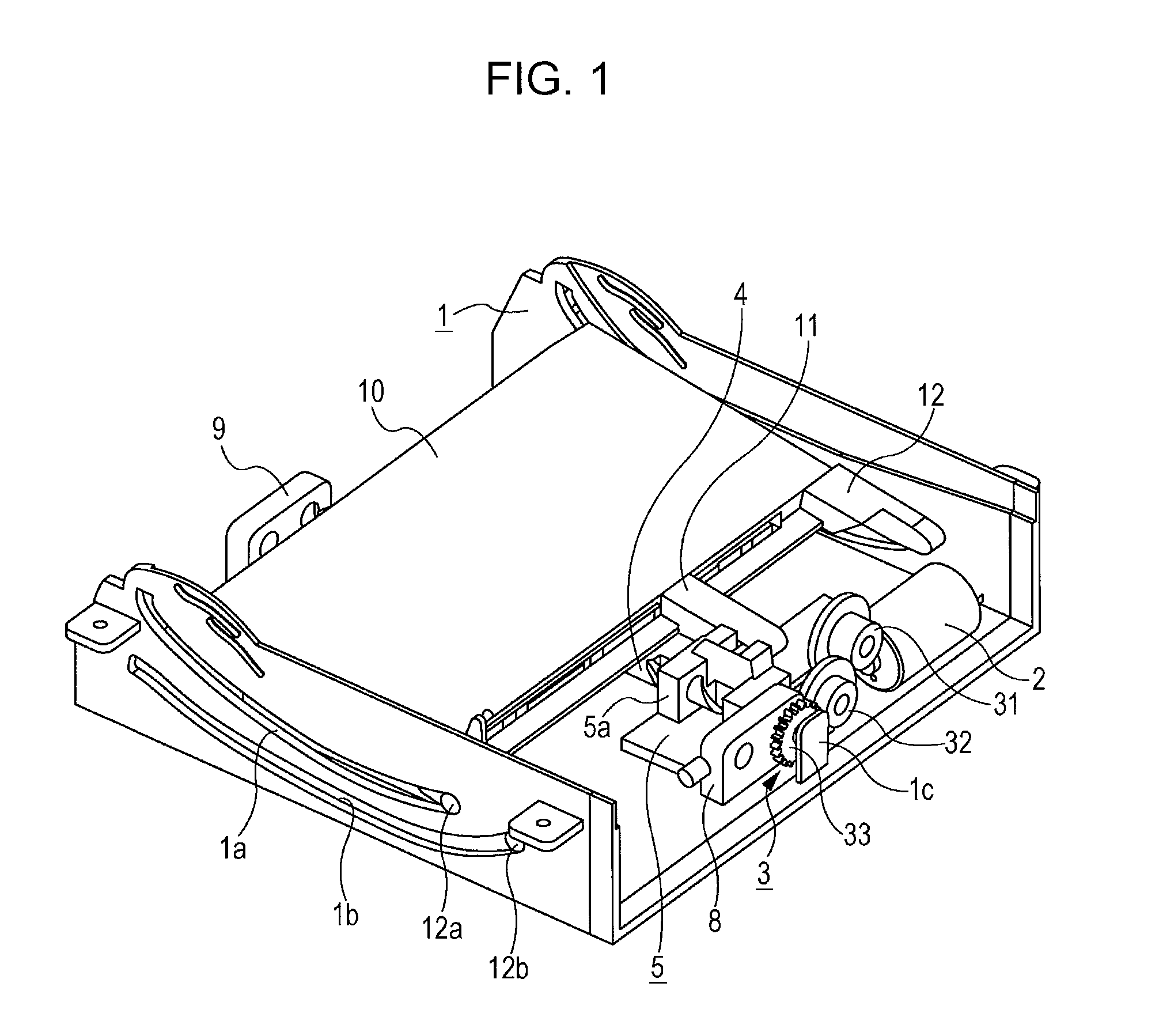
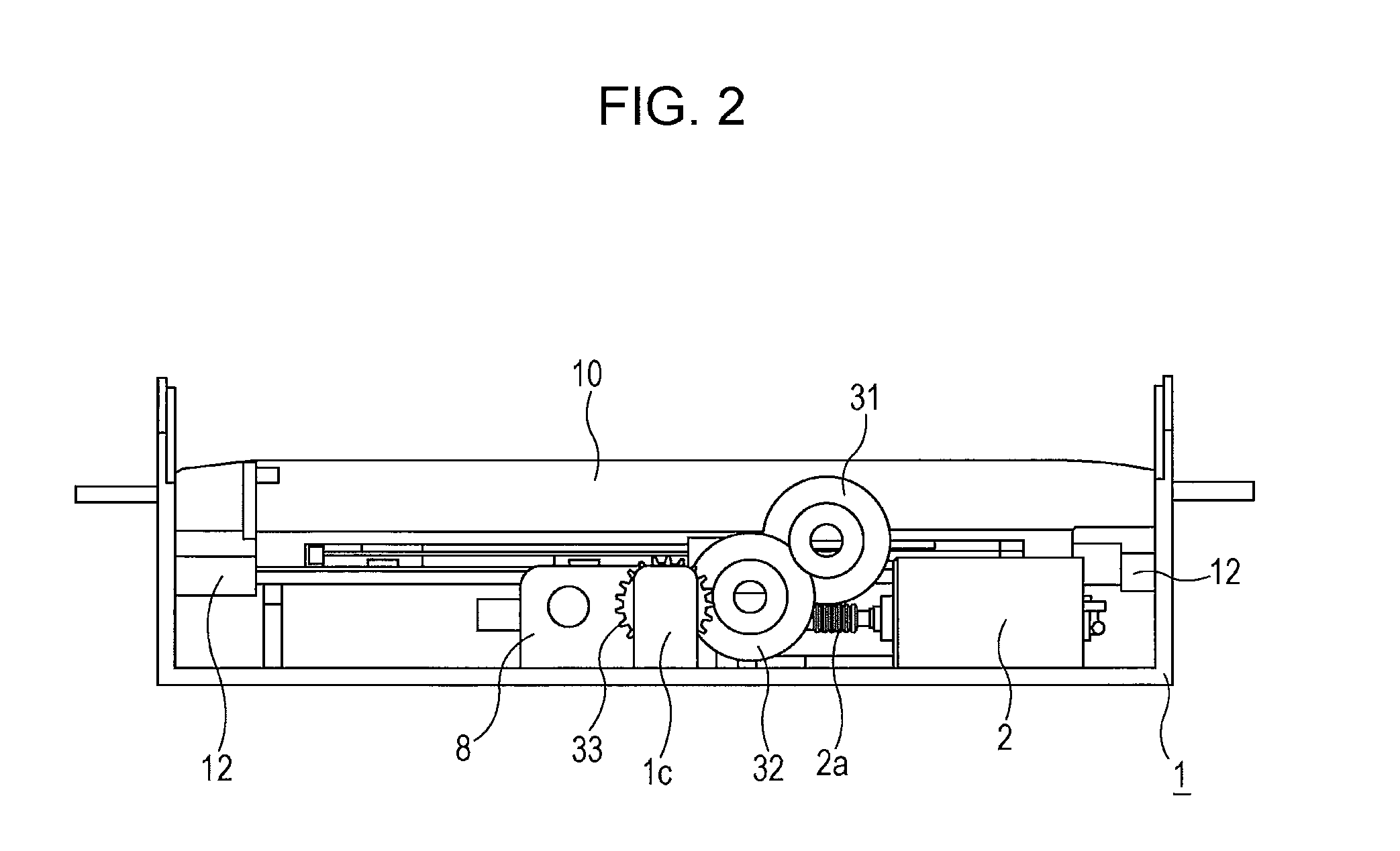
[0013]As described above, the facing surfaces of the first gear on the input side and the second gear on the output side are in a recess-protrusion engagement, the first gear is elastically urged toward the second gear by the spring member, and so the first and second gears can be rotated coaxially and integrally. Thus, the drive force of the motor can be reliably transmitted from the first gear through the second gear to the threaded rod. Since the display main body is rotatably connected to the slider that moves back and forth with the rotation of the threaded rod, the display main body can be moved smoothly, while being guided by cam grooves or the like, between a horizontal retracted position and a vertical raised position. Thus, the whole apparatus can be easily reduced in thickness.
[0014]If a pushing force tries to forcibly retract the display main body in the raised state and the slider rotates the threaded rod, the second gear rotates relative to the first gear that is not rotating, and thus the protrusions of the second gear gradually come out of the recesses of the first gear, and the first gear is displaced against the spring member away from the second gear. On the basis of the displacement of the first gear, the size of the pushing force is detected by the detection sensor. Thus, by appropriately controlling the motor according to the detection result, the operation required to move the display main body away from the pushing force can be performed quickly. Similarly, if a resisting force interferes with the raising of the display main body, this resisting force prevents the threaded rod and the second gear from rotating, and thus, as the first gear is rotated by the drive force of the motor, the protrusions gradually come out of the recesses, and the first gear is displaced against the spring member away from the second gear. Also in this case, on the basis of the displacement of the first gear, the size of the resisting force is detected by the detection sensor. Thus, by appropriately controlling the motor according to the detection result, the operation required to move the display main body away from the resisting force can be performed quickly. Thus, damage to the power transmission mechanism when an unwanted external force such as a pushing force or a resisting force is applied to the display main body can be prevented without the need to add a large clutch mechanism.
[0015]In the above-described configuration, the second gear may rotate coaxially and integrally with the threaded rod. Alternatively, the second gear may be in meshing engagement with a third gear that rotates coaxially and integrally with the threaded rod. In this case, the axis of the first and second gears can be offset with respect to the axis of the threaded rod. Thus, when the first gear is displaced against the spring member in the axial direction, there is no possibility that the reaction force displaces the threaded rod in the axial direction. Thus, the reliability is improved.

Problems solved by technology

For this reason, this type of on-vehicle display apparatus has a problem given that the configuration of the power transmission mechanism is complex, the number of components is large, and it is difficult to reduce the size and thickness of the apparatus.
Thus, the thickness of the whole apparatus cannot be reduced significantly.
In that case, there is a possibility that gears that constitute the power transmission mechanism of the on-vehicle display apparatus are subjected to an excessive force and damaged.
However, adding a clutch mechanism makes the structure larger, and thus makes it difficult to reduce the whole apparatus in thickness.
When the transmission pathway of an unwanted external force applied to the display main body is blocked by a clutch mechanism, there is a possibility that the clutch plate or the like slides and generates a rasping abnormal noise.

Method used


Image

  • On-vehicle display apparatus
  • On-vehicle display apparatus
  • On-vehicle display apparatus

Examples


Embodiment Construction

[0035]Embodiments of the present invention will now be described. First, an embodiment of the present invention will be described with reference to FIG. 1 to FIG. 13.

[0036]An on-vehicle display apparatus according to the first embodiment includes a display main body 10 that is an LCD or the like and that can be retracted in a horizontal position in a case 1 and can be raised in a vertical position in the front part of the case 1. The drive source that moves the display main body 10 between the retracted position and the raised position is a motor 2. The drive force of the motor 2 is transmitted to the display main body 10 through a gear train 3, a threaded rod 4, a slider 5, and other power transmission mechanisms. These power transmission mechanisms are disposed in the case 1 together with a circuit board (not shown) and other components. This circuit board is provided with a circuit that drives the display main body 10 and other components. This on-vehicle display apparatus is use...


PUM


Abstract

An on-vehicle display apparatus includes a motor, a gear train, a threaded rod, a slider screwed to the threaded rod, and a display main body rotatably connected to the slider. The lead angle of the threaded rod is set greater than the friction angle thereof. The gear train includes first and second gears facing each other. Protrusions provided on one of the first and second gears are fitted in recesses provided in the other. A spring member elastically urges the first gear toward the second gear. A detection sensor detects the size of an external force on the basis of the displacement of the first gear against the spring member in the axial direction. The motor is controlled on the basis of the detection result of the detection sensor such that the display main body is moved away from the external force.

Description

RELATED APPLICATION[0001]The present application claims priority to Japanese Application Number 2011-091354, filed Apr. 15, 2011, the entirety of which is hereby incorporated by reference.BACKGROUND OF THE INVENTION[0002]1. Field of the Invention[0003]The present invention relates to an on-vehicle display apparatus installed in an automobile for displaying TV programs, map information of a navigation system, and the like, and more specifically, to an on-vehicle display apparatus having a display main body that can be retracted when not in use.[0004]2. Description of the Related Art[0005]When this type of on-vehicle display apparatus is in use, the display main body can be raised to a position where the display main body can be easily viewed by the user. When the apparatus is not in use, the display main body can be retracted, for example, in the dashboard. Thus, the display main body not in use does not take up space in the car.[0006]In recent years, on-vehicle display apparatuses i...

Claims


Application Information

Patent Timeline
Patent Type & Authority Applications(United States)
IPC IPC(8): G06F1/16
CPCB60R11/0235H04N5/655H04N21/41422B60K2350/405B60R2011/0043B60R2011/0092B60K35/00B60R2011/0005B60K2360/66B60K35/22B60K35/53
Inventor KATO, KAZUNARI
Owner ALPINE ELECTRONICS INC
Learn More