Touch panel inspecting apparatus

a technology for touch panel inspection and apparatus, which is applied in the direction of instruments, error detection/correction, computing, etc., can solve the problems of considerable degradation in inspection efficiency and the inability of inspection devices to fill a need, and achieve the effect of improving inspection efficiency and easy and flexible force chang

Inactive Publication Date: 2015-07-30
NIDEC-READ CORPORATION
View PDF13 Cites 5 Cited by
  • Summary
  • Abstract
  • Description
  • Claims
  • Application Information

AI Technical Summary

Benefits of technology

[0017]An exemplary embodiment of the disclosure provides a touch panel inspecting apparatus having the following configuration. The touch panel inspecting apparatus includes a holding part, a pseudo finger, a contact position changing part, a set pressing force memory part, a pressing force regulating part, and an acquiring part. The holding part is configured to allow a touch panel, which is an inspection target, to be set thereon. The pseudo finger is configured to be contactable with the touch panel set on the holding part. The contact position changing part is configured to move the pseudo finger relative to the touch panel and to change a contact position of the touch panel with the pseudo finger. The set pressing force memory part is configured to store a set value of pressing force of the pseudo finger, in a changeable manner. The pressing force regulating part is configured to regulate the pressing force to bring the pseudo finger into contact with the touch panel, based on the set value stored in the set pressing force memory part. The acquiring part is configured to acquire an electric signal output from the touch panel.
[0018]Thus, the touch panel inspecting apparatus can inspect the touch panel, based on the electric signal acquired by the acquiring part, while easily and flexibly changing the force to bring the pseudo finger into contact with the touch panel, by changing the set value stored in the set pressing force memory part. Accordingly, the touch panel inspecting apparatus can quickly address a change of a touch panel to be inspected, a change of inspection conditions, and the like, and therefore can considerably improve inspection efficiency.
[0019]Preferably, the touch panel inspecting apparatus further includes a weight canceling part configured to apply, to the pseudo finger, force to bring the pseudo finger apart from the touch panel.
[0020]Thus, the touch panel inspecting apparatus can bring the pseudo finger into contact with the touch panel with force lighter than the self weight of the pseudo finger. Accordingly, the touch panel inspecting apparatus can inspect the touch panel under wider conditions than ever before.
[0021]In the touch panel inspecting apparatus, preferably, the set pressing force memory part is capable of storing a set value corresponding to zero pressing force of the pseudo finger.
[0022]Thus, the touch panel inspecting apparatus can bring about a state in which the pseudo finger is in contact with the touch panel with the zero pressing force. Accordingly, the touch panel inspecting apparatus can inspect the touch panel in a special state in which a mechanical load to be applied to the touch panel is substantially eliminated.

Problems solved by technology

The touch panel inspection device disclosed in JP 2003-303051 A is configured to evaluate the destruction durability performance of a touch panel, but is not configured to determine whether or not a touch panel is a defective.
However, if the inspection device disclosed in JP 2003-303051 A is adapted to conduct this inspection, a weight is replaced by a different one each time the pressing force of the pen member is changed, so that the inspection efficiency is considerably degraded.
For this reason, weakening the pressing force has a ceiling and, in actual fact, the inspection device cannot fill a need to inspect operation of the touch panel which is touched with considerably light force such as approximately zero gram.

Method used


Image

  • Touch panel inspecting apparatus
  • Touch panel inspecting apparatus
  • Touch panel inspecting apparatus

Examples


Embodiment Construction

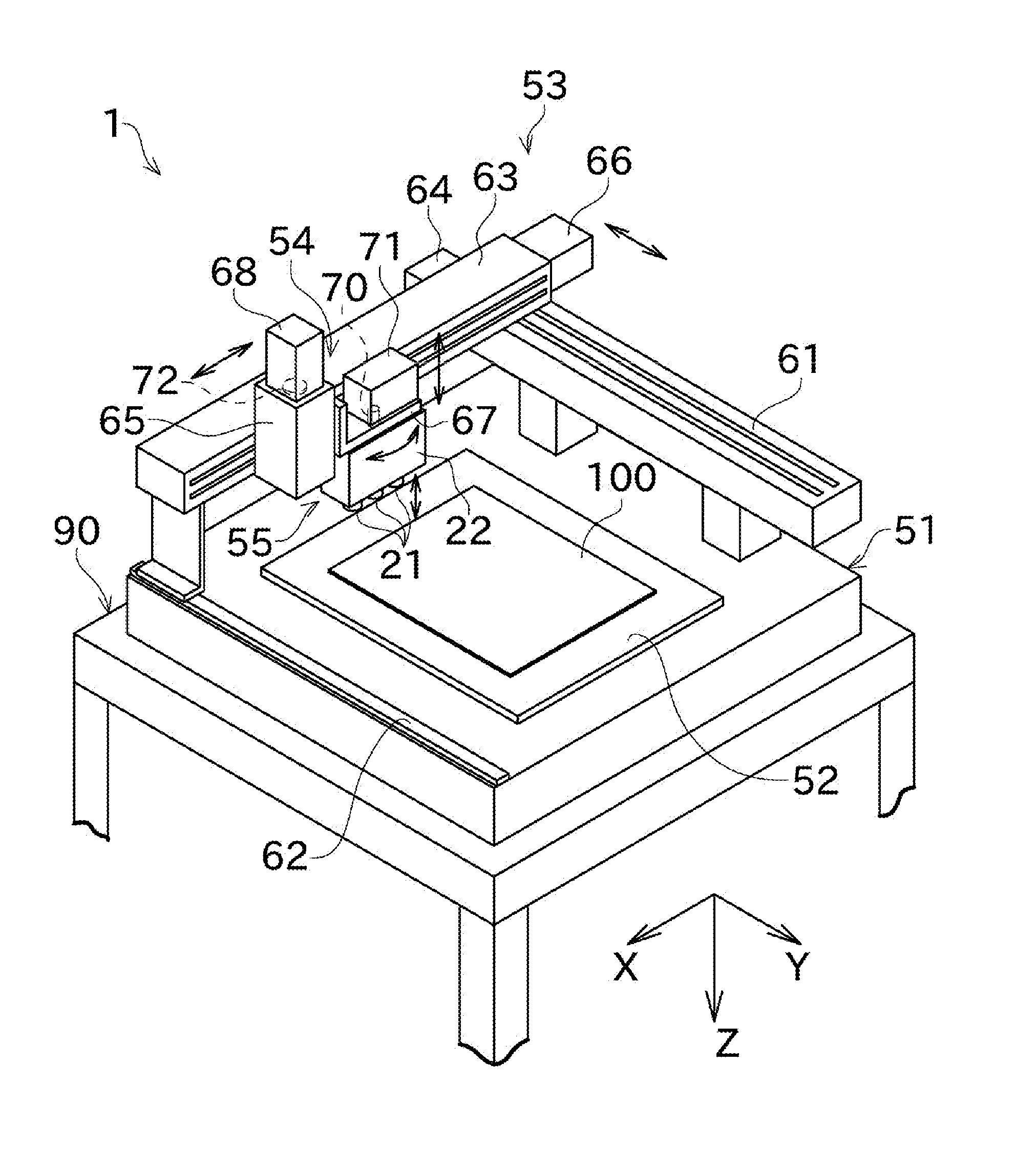
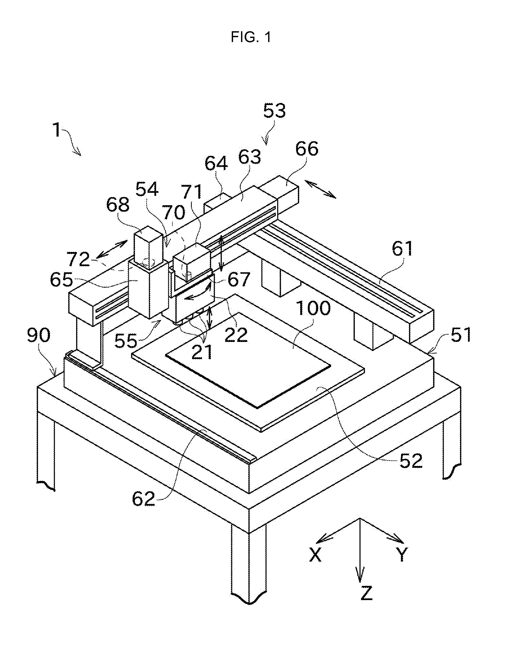
[0031]Various embodiments of the disclosure will be described below with reference to the drawings. FIG. 1 is a schematic perspective view illustrating an overall configuration of a touch panel inspecting apparatus 1 according to an exemplary embodiment.

[0032]The touch panel inspecting apparatus 1 illustrated in FIG. 1 is mounted on a horizontal workbench 90 in active use. The touch panel inspecting apparatus 1 includes a base 51, a workpiece holder (a holding part) 52, an X-Y movement mechanism 53, a Z movement mechanism 54, and a pseudo finger mechanism 55.

[0033]The base 51 has a horizontal upper surface, and an X axis and a Y axis which are orthogonal to each other are defined in a plane parallel with the horizontal upper surface. Moreover, a Z axis is defined in a direction perpendicular to the X-Y plane.

[0034]The workpiece holder (the holding part) 52 is fixed onto the upper surface of the base 51. The workpiece holder 52 has a horizontal flat plate shape. The workpiece holder ...


PUM


Abstract

A touch panel inspecting apparatus includes a workpiece holder, a pseudo finger, an X-Y movement mechanism, a memory part, an electric pneumatic regulator, and a panel signal acquiring part. The workpiece holder allows a touch panel, which is an inspection target, to be set thereon. The pseudo finger is contactable with the touch panel set on the workpiece holder. The X-Y movement mechanism moves the pseudo finger relative to the touch panel. The memory part stores therein a set value of pressing force of the pseudo finger, in a changeable manner. The electric pneumatic regulator regulates the pressing force to bring the pseudo finger into contact with the touch panel, based on the set value stored in the memory part. The panel signal acquiring part acquires an electric signal output from the touch panel.

Description

CROSS REFERENCE TO RELATED APPLICATION[0001]This application is based on and claims priority from Japanese Patent Application No. 2014-012396, filed on Jan. 27, 2014, the contents of which are hereby incorporated by reference in their entirety.BACKGROUND[0002]1. Technical Field[0003]This disclosure relates to a configuration of an apparatus for inspecting a touch panel.[0004]2. Related Art[0005]With the recent rapid widespread use of electronic appliances such as a smartphone and a tablet, there is an increasing demand for touch panel devices configured to detect a position touched by a human finger or with a stylus pen. Examples of the touch panel device include an electrostatic capacitance touch panel device, a pressure-sensitive resistive film touch panel device, and the like.[0006]A recent stylus pen has been provided with a pressure-sensitive sensor to realize a so-called writing pressure sensing function. A combination of this pressure-sensitive pen with a touch panel device a...

Claims


Application Information

Patent Timeline
Patent Type & Authority Applications(United States)
IPC IPC(8): G06F3/044G06F3/0354G06F3/041
CPCG06F3/044G06F3/03545G06F3/0414G06F11/2221G06F3/0446G01R31/26
Inventor SAKAMOTO, KOJIMATSUKAWA, TOSHIHIDEIWAMI, KOJIFUJITA, SHIGEKIHIKITA, OSAMU
Owner NIDEC-READ CORPORATION
Why Eureka
Try Eureka