
Engine suspension structure for two-wheeled motor vehicle

A technology for motorized two-wheeled vehicles and engines, which is applied to motor vehicles, motorcycles, bicycles, etc., can solve problems such as weight increase, and achieve the effects of improving support rigidity, reducing costs, and improving exhaust efficiency

Inactive Publication Date: 2011-10-26
HONDA MOTOR CO LTD
View PDF5 Cites 0 Cited by
  • Summary
  • Abstract
  • Description
  • Claims
  • Application Information

AI Technical Summary

Problems solved by technology

[0004] However, since the front part of the engine is mounted on one downpipe via a mounting plate, it is necessary to ensure better support rigidity of the engine when the weight of the engine increases due to, for example, a change in the model of the engine.

Method used


Image

  • Engine suspension structure for two-wheeled motor vehicle
  • Engine suspension structure for two-wheeled motor vehicle
  • Engine suspension structure for two-wheeled motor vehicle

Examples


Embodiment Construction

[0039] Hereinafter, preferred embodiments of the present invention will be described in detail based on the drawings.

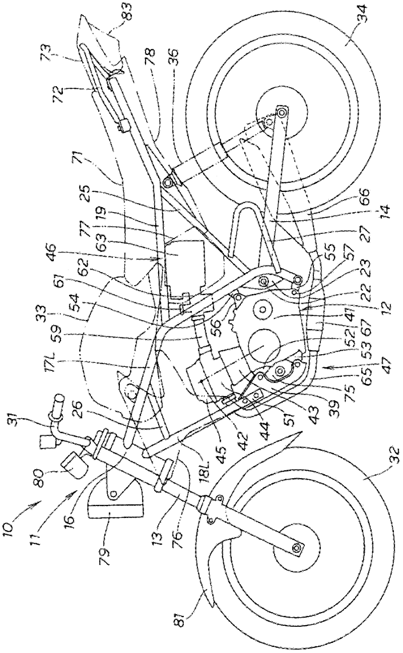
[0040] figure 1 The illustrated motorcycle 10 has: an engine 12 arranged at the central portion of the vehicle frame 11, a front fork 13 manipulably supported on the front end of the vehicle frame 11, and a front fork 13 supported swingably up and down at the rear lower portion of the vehicle frame 11. The left and right rocking arms 14.

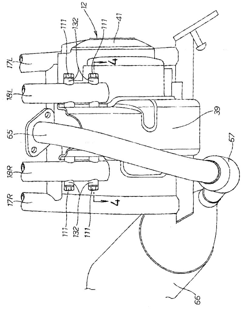
[0041] The frame 11 has left and right main frames 17L, 17R ( image 3 ); the left and right down frames 18L, 18R ( image 3 ), and the front end of the down frame 18L, 18R is mounted on the head pipe 16 below the left and right main frames 17L, 17R; The left and right sub-frames 25 between the respective rear lower parts of the main frame 17 and the respective intermediate parts of the left and right seat rails 19.

[0042] The left and right pivot plates 23 are provided on the lower portions of the left and right main...


PUM


Abstract

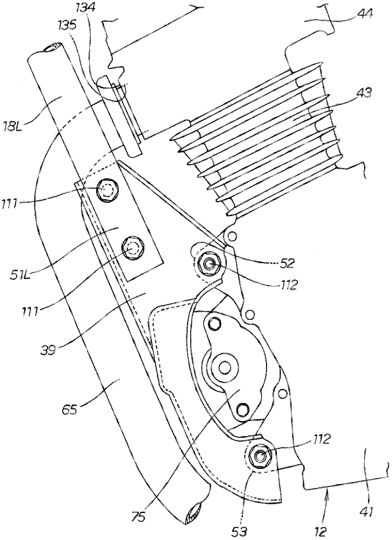
An engine suspension structure for a two-wheeled motor vehicle is disclosed. Left and right down frames (18L, 18R) spaced from each other in the vehicle's width direction extend downward from a vehicle body frame (11). A mount plate (39) is mounted so as to be sandwiched between the two, left and right down frames. An engine (12) is mounted to the mount plate.

Description

technical field [0001] The present invention relates to the improvement of the engine suspension structure of the motorcycle. Background technique [0002] As an engine suspension structure of a motorcycle having a downpipe supporting a front portion of an engine, for example, a structure disclosed in Patent Document 1 is known. Wherein, the drop tube constitutes the vehicle frame. [0003] In Patent Document 1, one downpipe extends downward in the front portion of the vehicle body, and the front portion of the engine is attached to the downpipe via a mounting plate. [0004] However, since the front portion of the engine is attached to one downpipe via a mounting plate, it is desired to ensure better support rigidity of the engine when the engine weight increases due to, for example, a model change of the engine. [0005] Patent Document 1: Japanese Patent Application Laid-Open No. 6-247365 Contents of the invention [0006] An object of the present invention is to pro...

Claims


Application Information

Patent Timeline
Patent Type & Authority Applications(China)
IPC IPC(8): B62K11/04B62M7/02
CPCB62K11/04
Inventor 横森哲人岛田隆之山口正昭藤山孝太郎
Owner HONDA MOTOR CO LTD
Learn More