Subframe for vehicle and bush attaching structure

A sub-frame and vehicle technology, applied in the substructure, vehicle components, transportation and packaging, etc., to achieve the effect of increasing the strength of the beam and increasing the strength

Inactive Publication Date: 2006-10-04
HONDA MOTOR CO LTD
View PDF3 Cites 23 Cited by
  • Summary
  • Abstract
  • Description
  • Claims
  • Application Information

AI Technical Summary

Problems solved by technology

For further improving the installation strength and supporting rigidity of the bracke

Method used


Image

  • Subframe for vehicle and bush attaching structure
  • Subframe for vehicle and bush attaching structure
  • Subframe for vehicle and bush attaching structure

Examples


Embodiment Construction

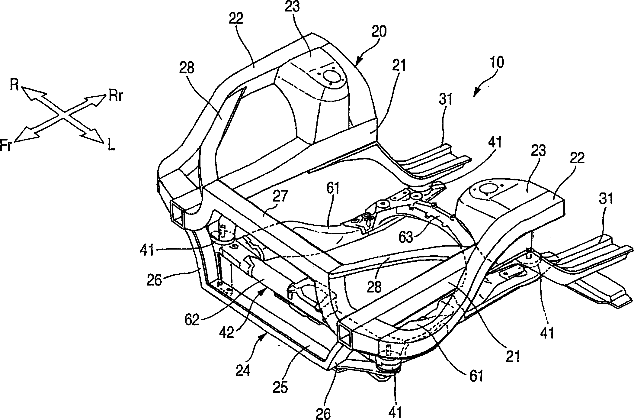
[0051] The best embodiment of the present invention will be described below with reference to the accompanying drawings. "Front", "Rear", "Left", "Right", "Up" and "Down" are the directions viewed by the driver, Fr means the front side, Rr means the rear side, L means the left side, R means the right side, CL represents the center of the vehicle body (the center of the vehicle width).

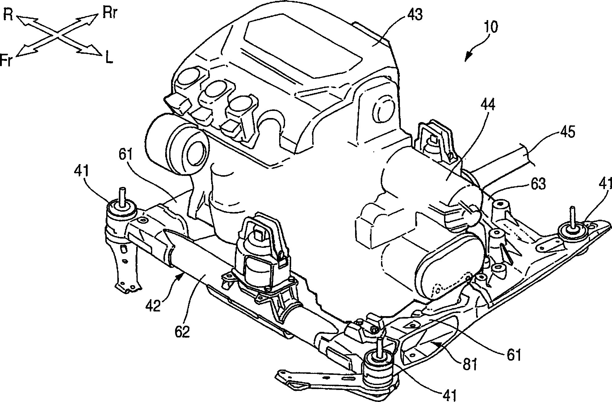
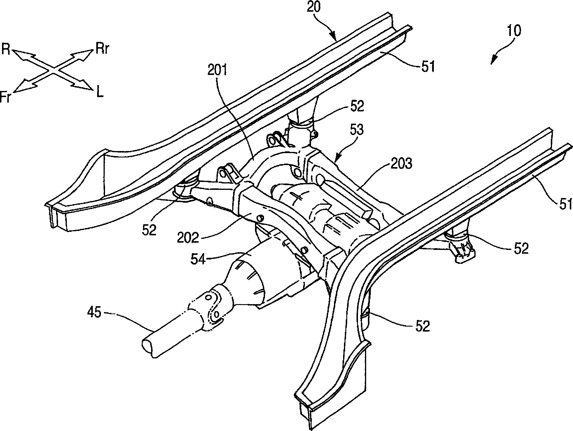
[0052] First, according to Figure 1 ~ Figure 3 The outline of the vehicle is explained.

[0053] figure 1 It is a perspective view of the front part of the vehicle of this invention. The vehicle frame (body) 20 of the vehicle 10 is a monocoque body, and its front structure mainly includes: left and right front side frames 21, 21 that are positioned at both sides of the front portion of the vehicle body and extend forward and backward to the vehicle body; The left and right upper frames 22,22 extending to the front and rear of the vehicle body on the outside and the top of the vehicle width...


PUM


Abstract

A front cross member 202 of a rear subframe 53 has a recessed portion 221 which is recessed continuously over a longitudinal direction thereof. The recessed portion 221 is formed at a lower portion of the cross member 202 and is recessed upwardly, and an elastic bush 240 is fitted in a resulting recess. The elastic bush 240 has an elastic element 243 which connects together an inner tube 241 and an outer tube 242 which surrounds the inner tube 231 and is mounted on the rear subframe 53 at the recessed portion 221 as a bracket. The bracket 221 has bracket plate portions 263a, 263b which each have a plane which is brought into contact with an end face of the inner tube and folded-back portions 235, 235. The bracket 221 is disposed in such a manner as to hold therein both ends of the inner tube 241 and is configured such that the elastic bush 240 is mounted thereon by passing a bolt 224 through the inner tube 241.

Description

technical field [0001] The invention relates to a subframe for a vehicle, which is installed on a vehicle body and used for installing a suspension device and a differential gear box. [0002] In addition, the present invention also relates to the improved technology of the sleeve installation structure for installing the elastic sleeve on the vehicle frame. Background technique [0003] A vehicle subframe is such a component. That is, for example, the cylindrical members are connected vertically and horizontally to form a "well"-shaped structure, and the necessary mounting parts are formed on this structure. As such a subframe for a vehicle, for example, cylindrical members for mounting to the vehicle body are formed at both ends of the vertical and horizontal members, and such a subframe for a vehicle is well known (for example, refer to JP-A-2003 -146240 publication (hereinafter referred to as patent document 1) (refer to page 4, figure 1 )). [0004] Patent Document ...

Claims


Application Information

Patent Timeline
IPC IPC(8): B62D21/00B60G7/00B60G7/02B62D21/11
CPCB60G2206/8103B60G2206/601B60G2204/41B60G2204/4302B60G7/02B60G2204/143
Inventor 小川努岩崎晴之堀出永井裕一秋山浩木村邦彦
Owner HONDA MOTOR CO LTD
Why Eureka
Try Eureka