Cylindrical roller bearing

a cylindrical roller bearing and roller bearing technology, applied in the direction of rolling contact bearings, shafts and bearings, rotary bearings, etc., can solve the problems of reducing the equalization capacity, difficult to obtain the level of non repeatable run-out (nrro) required for the main spindle of a machine tool, and abnormal abrasion of the cage, so as to reduce the number of non repeatable runs. , the effect of suppressing the increase in the bearing temperatur

Active Publication Date: 2005-03-31
NTN CORP
View PDF1 Cites 24 Cited by
  • Summary
  • Abstract
  • Description
  • Claims
  • Application Information

AI Technical Summary

Benefits of technology

[0066] With a cylindrical roller bearing according to the present invention described above, in a cylindrical roller bearing comprising a so-called comb type cage made of a synthetic resin, it is possible to prevent abnormal contact between the tip end inner circumferential sections of the pillars and the rolling contact surface of the cylindrical rollers during high speed rotation, thereby preventing abnormal abrasion of the cage, suppressing increases in the bearing temperature, and reducing non repeatable run-out (NRRO).
[0067] Furthermore, with the cylindrical roller bearing according to the present invention, because a roll-off section with a first lubricant reservoir is formed on the circumferential direction side faces of the pillars of the cage, even if the lubricant such as grease or oil which coats the cylindrical rollers is scraped off by the circular arc surface of the pillars during rolling of the rollers, for example, the lubricant is replenished from these first lubricant reservoirs of the roll-off sections formed on the pillars, and consequently there is much less likelihood of poor lubrication between the pillars and the cylindrical rollers. Because satisfactory lubrication properties can be ensured even during high speed rotation, it is possible to prevent, to a large degree, problems such as seizing and the like caused by poor lubrication.
[0068] In addition, with the cylindrical roller bearing according to the present invention, in a so-called comb type cylindrical roller bearing comprising a cage made of a synthetic resin, because the length in the axial direction of the annular section of the cage is set to between 30 and 40% of the length in the axial direction of the cylindrical rollers, the pillars are supported by an annular section with relatively high rigidity, meaning the support rigidity is improved, and even when the pillars begin to undergo outward elastic deformation due to the centrifugal force generated during rotation, an unduly large amount of elastic deformation can be prevented from occurring at the base end of each pillar, and consequently, elastic deformation of the entire pillar can be suppressed.

Problems solved by technology

However, in a synthetic resin cage of this construction, because the tips of the pillars are free edges, the pillars undergo a comparatively large amount of outward elastic deformation due to the effect of centrifugal force generated during rotation, particularly at high rotation speeds, and the inner circumferential sections of these tips on the circumferential direction side faces can come into strong contact (abnormal contact) with the rolling contact surfaces of the cylindrical rollers, causing a deficiency of oil film between the contacting parts, which can generate abnormal abrasion or a rise in the bearing temperature.
However, for the reasons described below, with the cylindrical roller bearings disclosed in the patent references 1 and 2, it is difficult to obtain the level of non repeatable run-out (NRRO) required for the main spindle of a machine tool.
An increase in this pocket gap g causes a reduction in the equalization capacity of the cylindrical roller and run-out of the center of revolution of the cylindrical roller, and non repeatable run-out occurs, leading to unstable shaking of the inner ring.
In particular, with roller guiding cages, increasing the degree of freedom of the cage in the radial direction produces locations where the pocket gap g increases and locations where the pocket gap g shrinks, and the positions of these locations are not constant, which increases the degree of non repeatable run-out.
This non repeatable run-out (NRRO) increases in proportion to the number of revolutions, and causes a variety of problems, including a deterioration in the machining accuracy of tools mounted to the main spindle of the machine tool.
However, while a cylindrical roller bearing according to this conventional design demonstrates adequate capabilities at low rotation speeds, at high rotation speeds there is a danger of elastic deformation of the pillars 14b of the cage 14 causing the bearing temperature to rise excessively.
However, when a simple straight surface 14b12 is formed on the circumferential direction side face 14b1 of the pillar 14b, as in the cage 14 of the cylindrical roller bearing disclosed in the patent references 1 and 2, contact during rotation, and particularly contact or sliding during rotation over long periods of time, increases the probability of a deficiency of oil film occurring between the pillar 14b and the cylindrical roller 13, which inevitably leads to a deterioration in the lubrication properties.
Despite this, the above patent references give no consideration to countermeasures for reliably preventing deterioration of the lubrication properties, and there is not even any indication or suggestion that the inventors were aware of such a problem.

Method used


Image

  • Cylindrical roller bearing
  • Cylindrical roller bearing
  • Cylindrical roller bearing

Examples


first embodiment

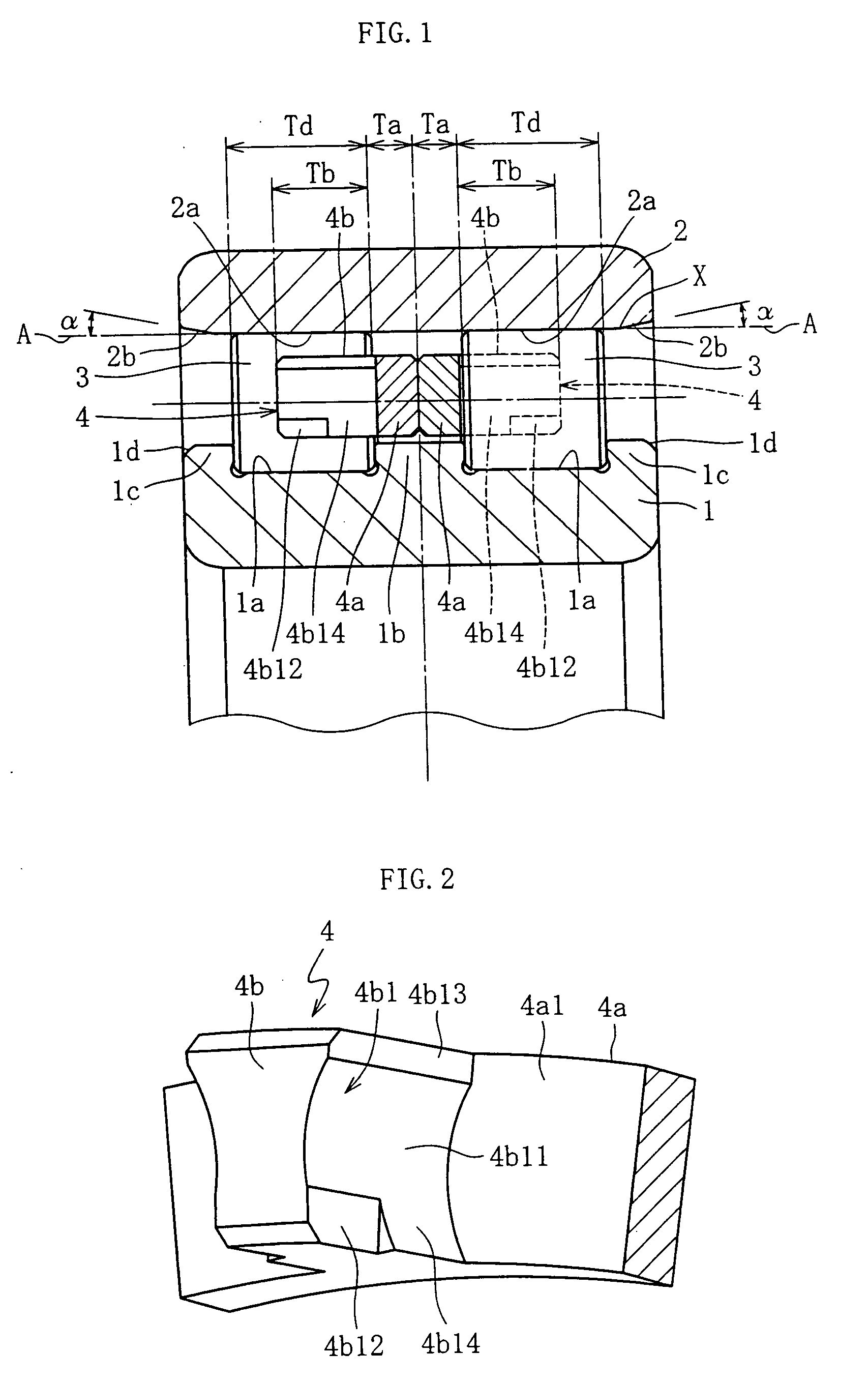
[0095]FIG. 1 shows a double row roller bearing according to a In the spindle device of a machine tool, this double row roller bearing is a device that supports the spindle, which is driven rotationally at high speed, in a freely rotatable manner relative to the housing. The roller bearing comprises an inner ring 1 having a double row of raceway surfaces 1a, an outer ring 2 having a double row of raceway surfaces 2a, a double row of cylindrical rollers 3 disposed between the raceway surfaces 1a of the inner ring 1 and the raceway surfaces 2a of the outer ring 2 in a freely rollable manner, and a pair of cages 4 made of a synthetic resin which support each of the cylindrical rollers 3. A central flange 1b is provided at the center, in the axial direction, of the inner ring 1, and outer flanges 1c are provided at both ends.

[0096] Chamfered sections 2b are formed at both outside ends in the axial direction of the raceway surfaces 2a of the outer ring 2, and relatively smaller chamfered...

seventh embodiment

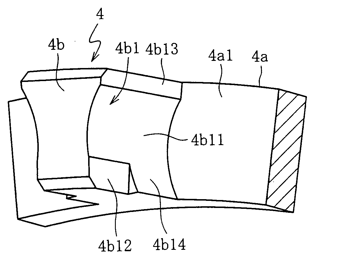
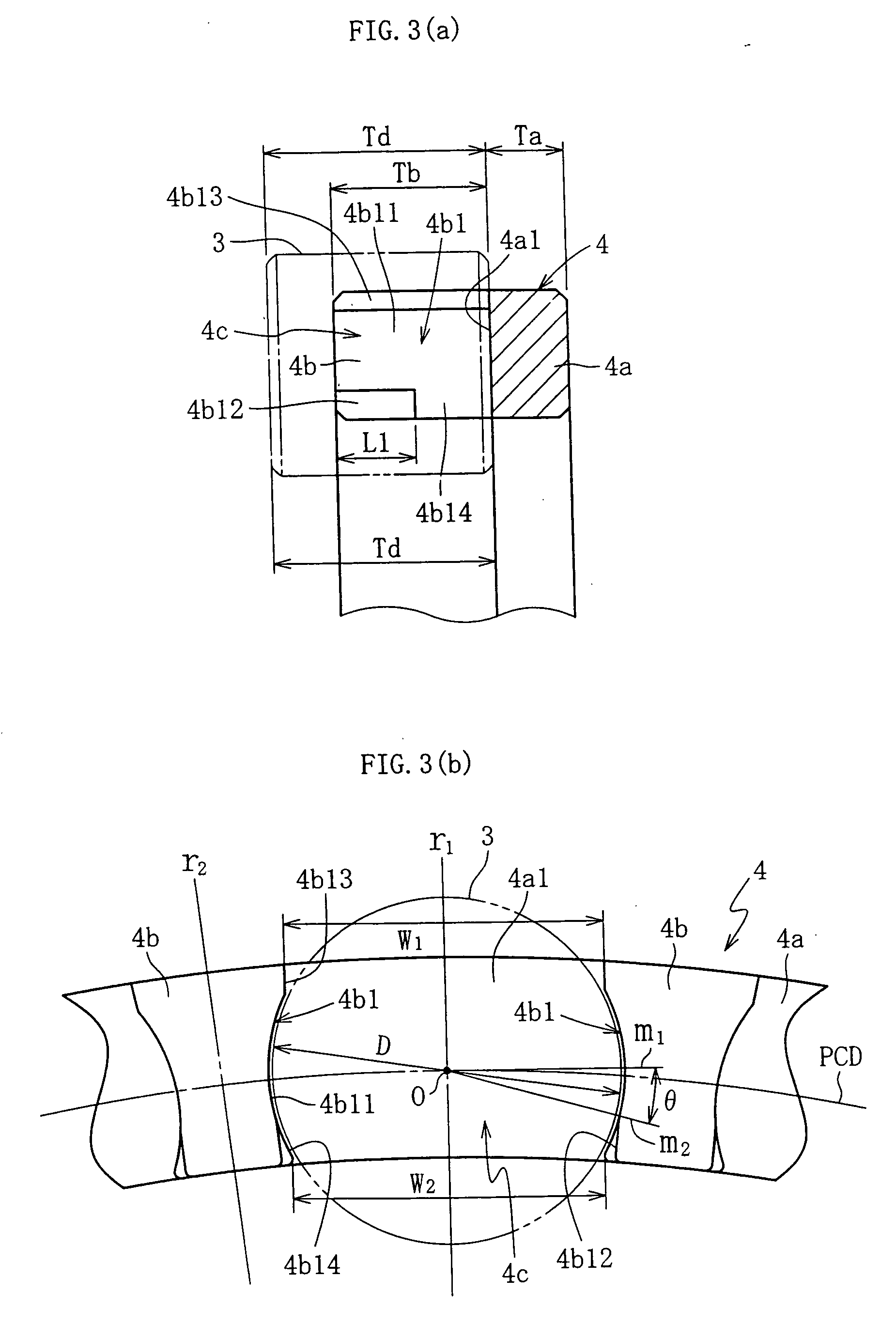
[0139] As shown in FIG. 13, in this seventh embodiment, the cage 4 is a rolling element guided cage, which rotates during bearing rotation with the inner circumferential direction side faces 4b1 of the pillars 4b guided while in contact with the rolling contact surface of the cylindrical rollers 3. When the rotation of the bearing reaches a predetermined speed, and centrifugal force causes the pillars 4b to undergo outward elastic deformation, the base end inner circumferential sections (the roller guide sections) 4b14 of the circumferential direction side faces 4b1 of the pillars 4b are displaced in a direction that reduces the pocket gap between the pillars 4b and the rolling contact surface of the cylindrical rollers 3 (that is, toward the outside diameter along the circumferential direction centerline r2) to guide the rolling contact surface of the cylindrical rollers 3. As a result, a favorable equalization capacity of the cylindrical rollers 3 is ensured, and the non repeatabl...

eighth embodiment

[0142] As shown in FIG. 16 and FIG. 17, in the cage 4 second lubricant reservoirs 4b22 comprising straight grooves are formed in the circular arc surfaces 4b11 of the pillar 4b in a separate position on the outer circumferential side of the roll-off sections (first lubricant reservoir sections) 4b12. These second lubricant reservoirs 4b22 are provided on the outer circumferential side of the pocket PCD in the form of grooves that are open only at the tip. Furthermore, each second lubricant reservoir 4b22 is formed from the tip of the pillar 4b, along the direction of the center axis Z, to a point partway to the base end section, and the length in the axial direction of the second lubricant reservoir is longer than that of the first lubricant reservoir 4b12.

[0143] Specifically, as shown in FIGS. 18(a) and 18(b), the length T2 in the axial direction of the second lubricant reservoir 4b22 is between 40 and 60%, and is preferably 50%, of the length Td in the radial direction of the cyl...


PUM


Abstract

A cage of a cylindrical roller bearing includes an annular section, a plurality of pillars that extend axially in an integrated, continuous manner from the inside surface of the annular section, and a plurality of pockets, which are formed between the inner circumferential direction side faces of adjacent pillars, and hold the cylindrical rollers in a freely rotatable manner. The circumferential direction side faces of the pillars incorporate a circular arc surface formed in both the inside and outside diameter directions from the pocket PCD which passes through the pocket center of the pocket, and a roll-off section (lubricant reservoir) provided at the tip end inner circumferential section.

Description

BACKGROUND OF THE INVENTION [0001] 1. Field of the Invention [0002] The present invention relates to a cylindrical roller bearing comprising a cage made of a synthetic resin, and particularly to a cylindrical roller bearing used to support a rotating member that rotates at high speed, such as the main spindle in a machine tool. [0003] 2. Description of the Related Art [0004] It is well known that in machine tools such as machining centers, CNC lathes, and milling machines, the main spindle is usually supported by a bearing in a freely rotatable manner relative to the housing. The orientation of this main spindle is divided into two broad categories, vertical (where the axis lies along the vertical) and horizontal (where the axis lies along the horizontal), depending on the type of machine. Furthermore, although dependent on the actual conditions of use, oil lubrication such as grease lubrication and air oil lubrication and the like are typically used as the lubricating method for th...

Claims


Application Information

Patent Timeline
Patent Type & Authority Applications(United States)
IPC IPC(8): F16C19/28F16C33/46F16C33/49F16C33/66
CPCF16C19/28F16C33/467F16C33/6614F16C33/498F16C33/6611F16C33/485
Inventor YAMAMOTO, NAOTAMIZUTANI, MAMORU
Owner NTN CORP
Why Eureka
Try Eureka