Roller head for a resistance welding machine

a welding machine and roller head technology, applied in the direction of resistance welding apparatus, domestic vessels, applications, etc., can solve the problems that the construction and arrangement of the electrode rollers is not suitable for the welding of the container body, and achieve the effects of reducing the bearing temperature, good welding effect and convenient manufacturing

Active Publication Date: 2015-05-14
SOUDRONIC
View PDF12 Cites 0 Cited by
  • Summary
  • Abstract
  • Description
  • Claims
  • Application Information

AI Technical Summary

Benefits of technology

[0006]The double-sided cooling of the bearings which is thereby achieved enables a reduced bearing temperature to be achieved. External cooling has previously not been considered by the person skilled in the art for roller heads of this kind which are used for welding can bodies. It appears, however, that this measure offers considerable advantages and is superior to forcing the pure internal cooling and / or the use of high-quality lubricants.
[0007]It is preferred that the arrangement of the coolant channels in the interior of the bearing outer housing comprises a plurality of coolant channels which radiate outwards from the centre of the bearing outer housing. Preferably, these radial channels lead to a ring-shaped coolant channel in the interior of the bearing outer housing which is located remotely from the centre of the bearing outer housing in the region of the outer edge of the bearing outer housing. This results in good cooling while the bearing outer housing is easy to manufacture. In particular, four or more outwards radiating coolant channels are provided.

Problems solved by technology

This construction and arrangement of the electrode rollers is not suitable for the welding of container bodies which necessitates that one of the roller heads is working inside of the body and the other roller head outside of the body.

Method used


Image

  • Roller head for a resistance welding machine
  • Roller head for a resistance welding machine
  • Roller head for a resistance welding machine

Examples


Embodiment Construction

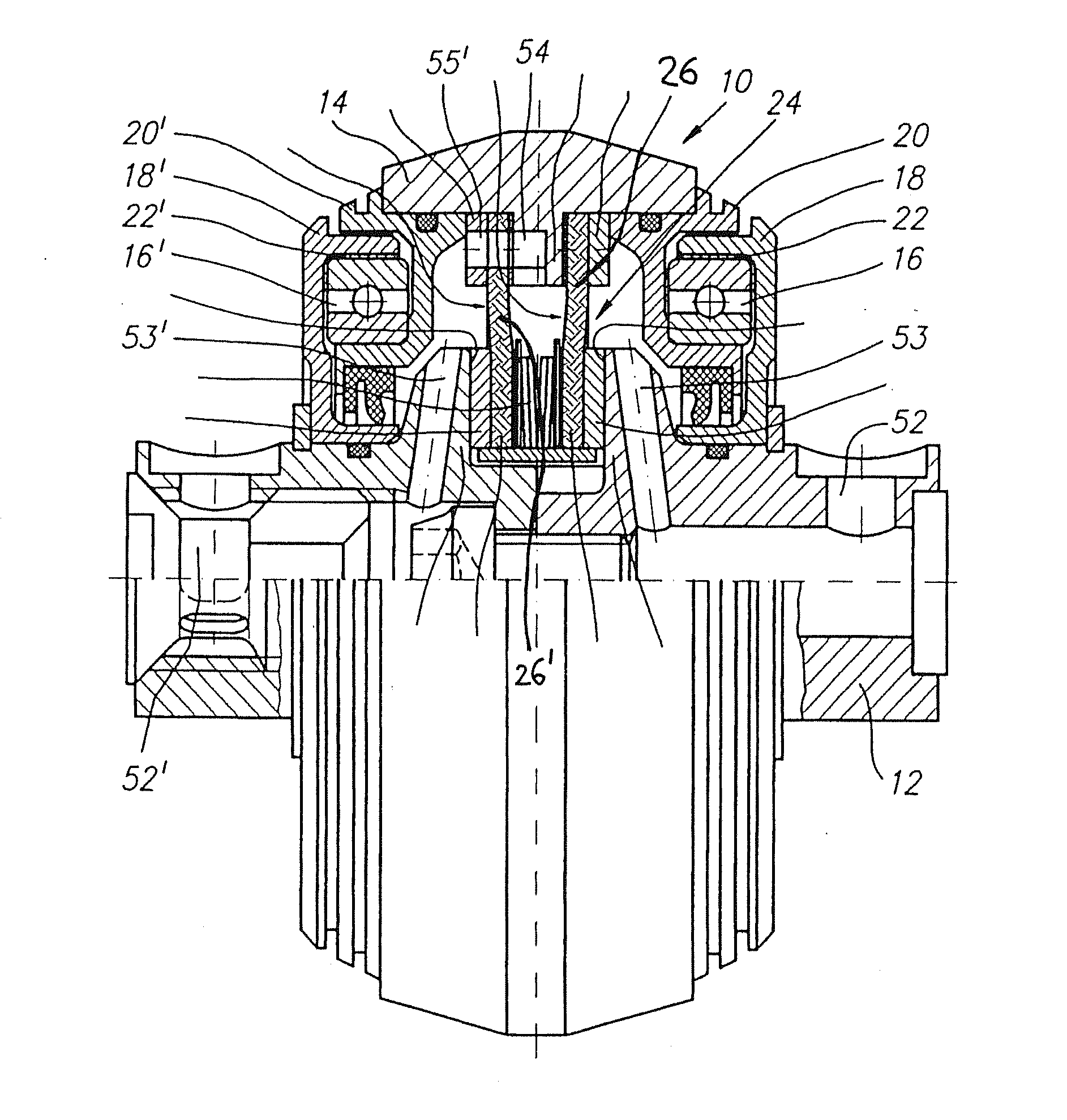
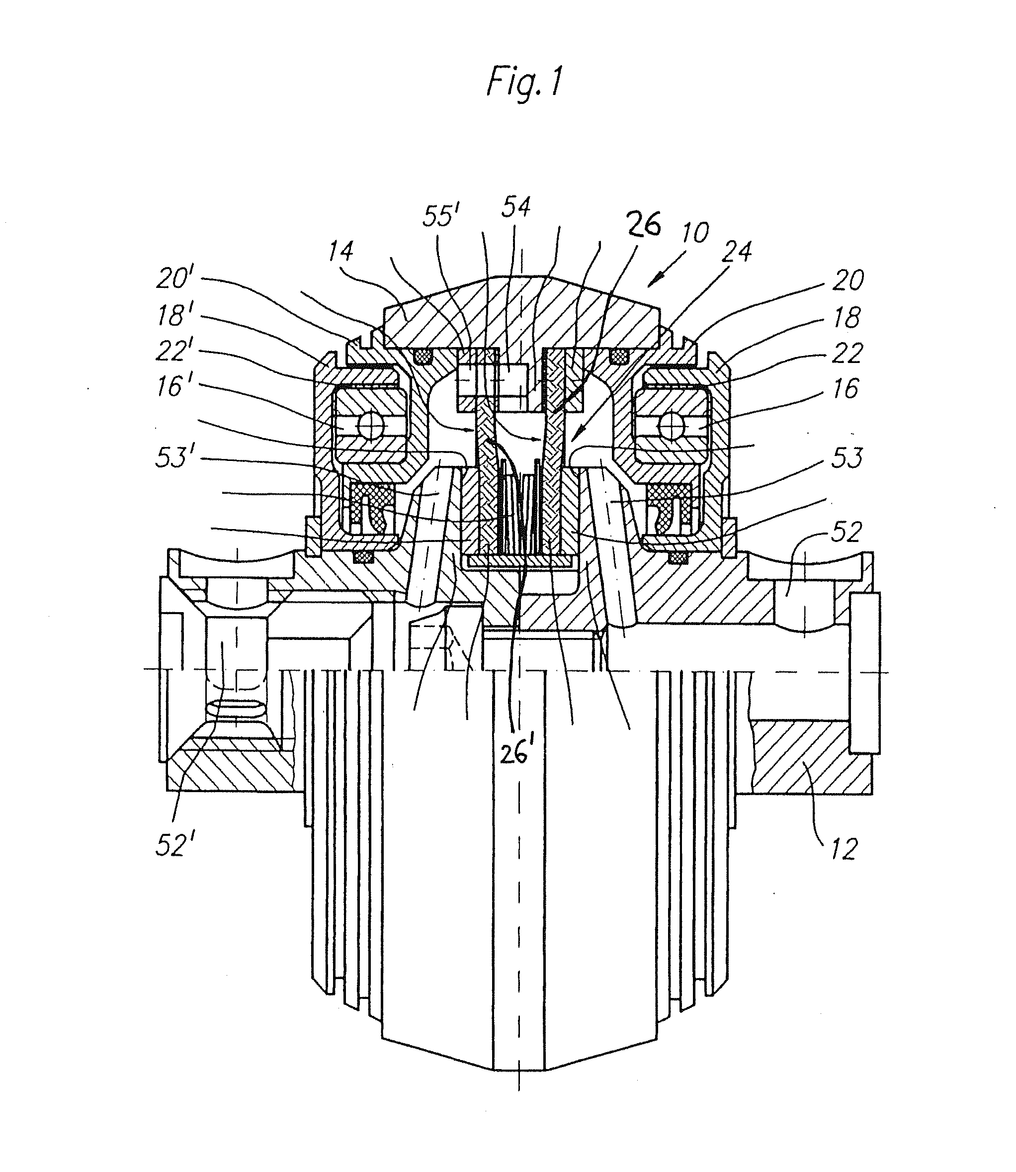
[0018]The design of a roller head according to the prior art, in particular in accordance with DE 40 20 182 C1 is explained with reference to FIG. 1. FIG. 1 shows the roller head designated overall by 10 for a resistance welding machine for resistance roller seam welding of can bodies. The roller head 10 is shown in section above its axis of rotation and, in this example, has a stator 12 in the form of a two-part axis on which a rotor 14 is rotatably mounted by means of roller bearings 16, 16′. The same references but with a dash in each case designate the other part of a pair of identically designed parts. For mounting by means of the roller bearings, the roller head 10 has bearing outer housings 18, 18′ fixed to the stator 12 and bearing inner housings 20, 20′ fixed to the rotor 14, between which are arranged the roller bearings 16, 16′ (here shown as ball bearings). The bearing outer and bearing inner housings 18, 18′ and 20, 20′ respectively are made from non-rusting, anti-magne...


PUM

PropertyMeasurementUnit
thicknessaaaaaaaaaa
operating temperaturesaaaaaaaaaa
temperatureaaaaaaaaaa

Abstract

With a roller head (10) of a resistance seam welding machine, which roller head has a stator (12) and a rotor (14), the bearing outer housing (18, 18′) is cooled by means of channels (2, 2′) provided in its interior. This increases the life of the roller head.

Description

CROSS REFERENCE TO RELATED APPLICATIONS[0001]This application is entitled to the benefit of and incorporates by references subject matter disclosed in International Patent Application No. PCT / CH2013 / 000090, filed on May 28, 2013 and Swiss Patent Application No. 769 / 12 filed on Jun. 4, 2012.TECHNICAL FIELD[0002]The invention relates to a roller head for a resistance seam welding machine. Further, the invention relates to a resistance seam welding machine and a method for resistance seam welding with roller heads of this kind.PRIOR ART[0003]A roller head of the kind mentioned in the introduction is disclosed in DE-A-40 20 182 C1. Such roller heads have proved their worth. The service life of the roller heads in operation is substantially determined by the roller bearings between rotor and stator. These bearings are cooled from the inside of the roller head by the coolant circulating within the roller head which dissipates heat from the bearing via the bearing inner housing. The lubric...

Claims


Application Information

Patent Timeline
Patent Type & Authority Applications(United States)
IPC IPC(8): B23K11/30B23K11/087
CPCB23K11/0873B23K11/3045B23K11/0876B23K2101/125
Inventor DIETERICH, DANIEL
Owner SOUDRONIC
Why Eureka
Try Eureka