Auto heat radiator frame support structure

A technology of support structure and radiator, which is applied in the arrangement of cooling combination of power plant, vehicle components, power plant and other directions, which can solve the problems of difficulty in realization and long distance.

Inactive Publication Date: 2006-12-13
MAZDA MOTOR CORP
View PDF2 Cites 20 Cited by
  • Summary
  • Abstract
  • Description
  • Claims
  • Application Information

AI Technical Summary

Problems solved by technology

[0006] In addition, when the radiator frame is arranged approximately immediately behind the bumper reinforcement as in Patent Document 2, the front portion of the side frame portion of the radiator frame can be supported by the bumper reinforcement, but the heat radiation The distance between the side frame portion of the radiator frame and the body side parts such as the fender becomes longer, so the side pillars of Patent Document 1 are provided on the side of the side frame portion of the radiator frame to make the vehicle body more rigid while ensuring the support rigidity. The method of supporting the side parts will be difficult to achieve
Especially for vehicles with long headlights in the front-to-rear direction, the front end of the fender is located relatively rearward, so the above-mentioned problems are more prominent

Method used


Image

  • Auto heat radiator frame support structure
  • Auto heat radiator frame support structure
  • Auto heat radiator frame support structure

Examples


no. 1 Embodiment approach

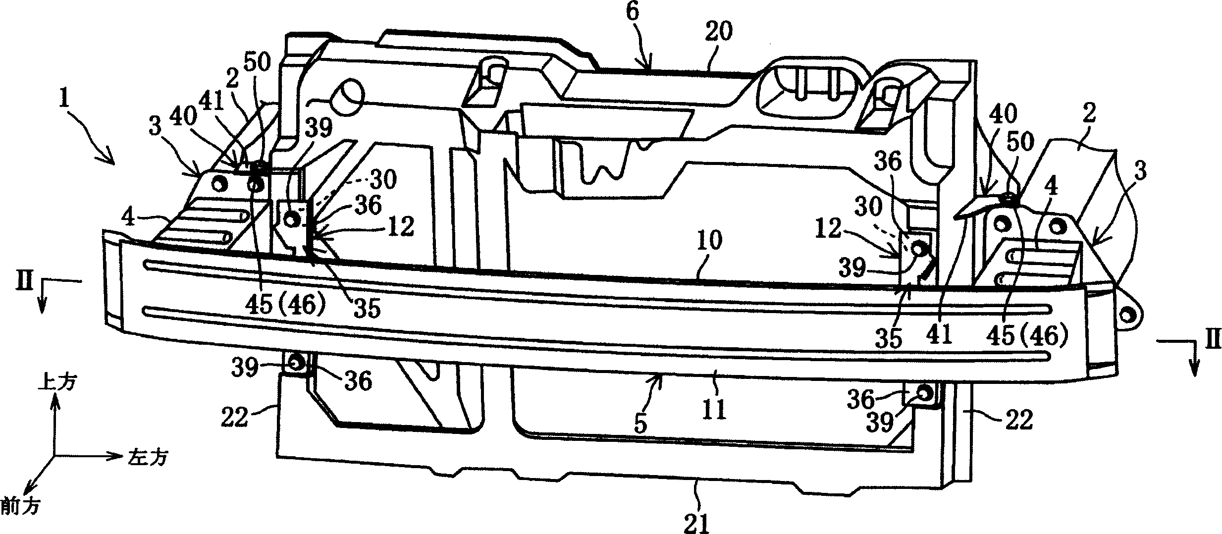
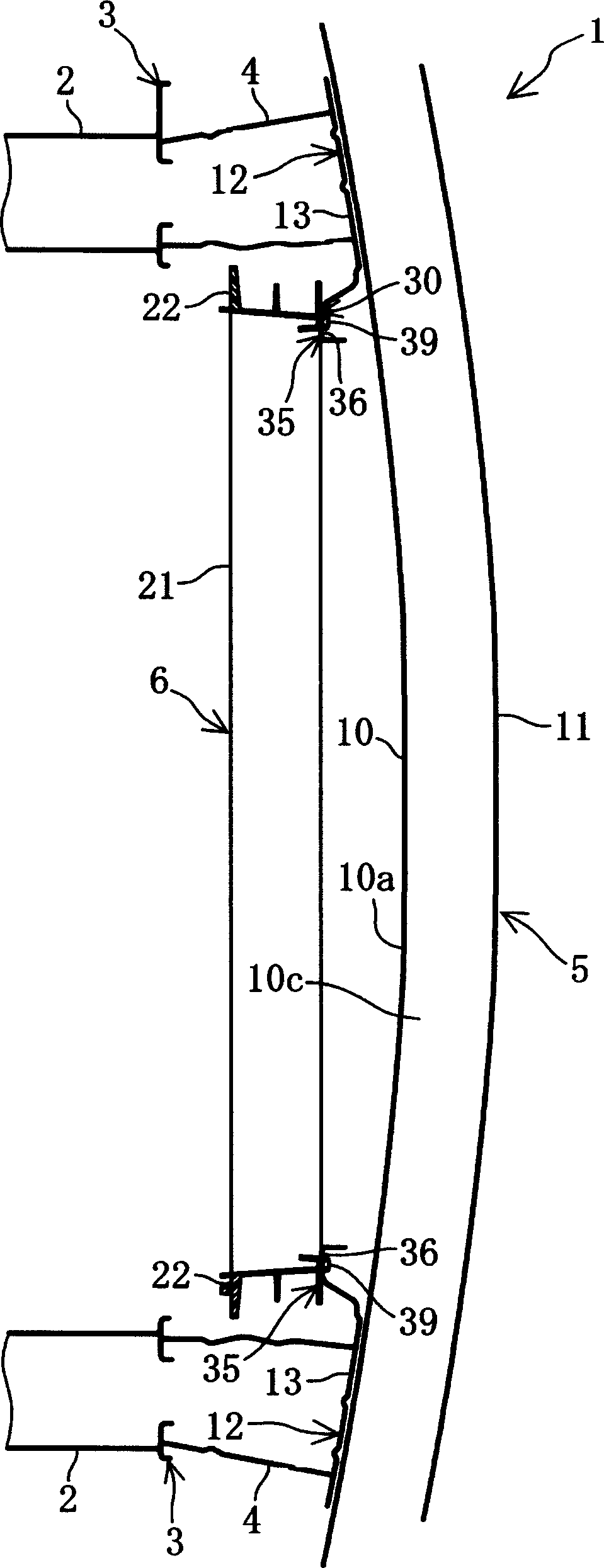
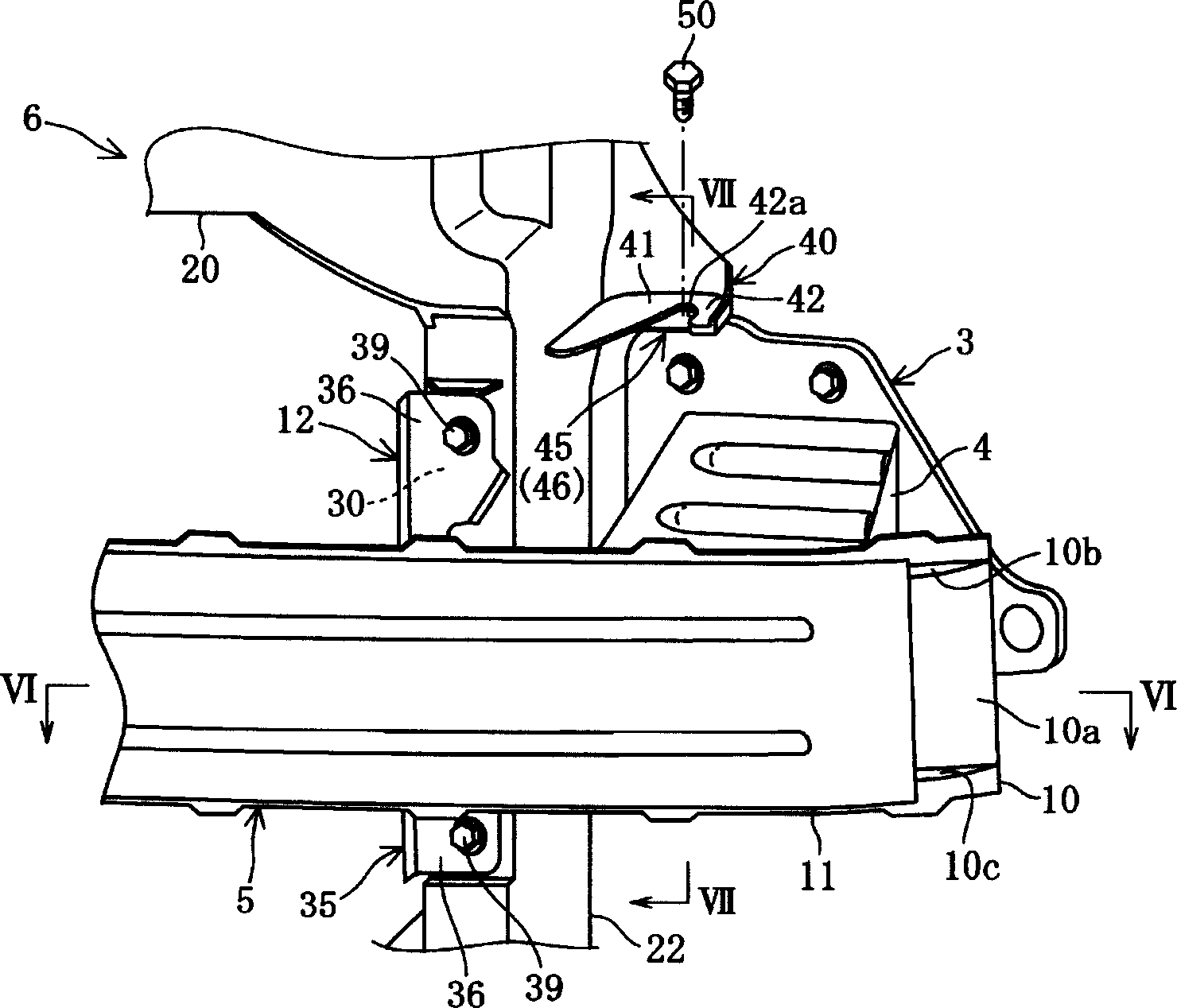
[0047] like figure 1 , figure 2 As shown, the front part 1 of the vehicle body is provided with a left and right pair of front longitudinal beams 2 and 2 extending in the front and rear direction, a left and right pair of crash boxes 4 and a bumper reinforcement 5, wherein the left and right pair of crash boxes 4 are respectively passed through A pair of left and right flange members 3, 3 are connected to the front ends of the front side members 2, 2 and extend forward from the front side members 2, 2; the bumper reinforcement 5 extends along the vehicle width direction and is connected to the crash box 4 at the front end. A radiator frame 6 made of synthetic resin having a "mouth" shape (rectangular frame shape) is supported and attached to the vehicle body front portion 1 described above.

[0048] The pair of front side members 2, 2 described above extend in the front-rear direction and are provided at a predetermined distance in the vehicle width direction, the flange 2a...

no. 2 Embodiment approach

[0073] The radiator frame support structure of the second embodiment is a radiator frame support structure obtained by partially modifying the vehicle body front portion 1 including the radiator frame support structure of the first embodiment. Therefore, the same reference numerals are assigned to the same components as those in the first embodiment, and description thereof will be omitted.

[0074] As shown in Figure 9~ Figure 14 As shown, in the vehicle body front portion 1A of the second embodiment, a flange member 3A is joined (welded) to the rear end portion of a crash box 4A, and the flange 2 a and the flange member 3A are joined by bolts / nuts 3A. The front end portion of the crash box 4A is directly joined to the bumper reinforcement 5 , therefore, an extension portion 4Aa extending forward is formed at the front end portions of the upper and lower walls of the crash box 4A, and the upper and lower extension portions 4Aa, 4Aa are welded to each other. The upper wall 1...


PUM


Abstract

The invention discloses a radiator bracket supporting structure which comprises left and right flange components (3) equipped with extending part (46); a security bar enhancing component (5) with a first supporting part (35) for the first part (30) constituted by the radiator bracket (6) and side bracket part (22), a second supporting part (45) constituted by the flange components (3) and the extending part (46) for supporting the second part (40) except for first part (30).

Description

technical field [0001] The present invention relates to a radiator frame support structure that supports a radiator frame at the front of a vehicle body of an automobile. Background technique [0002] Generally, a car is equipped with a radiator frame (shroud) for installing a radiator or a condenser. The radiator frame has an upper frame, a lower frame, and left and right side frames, and is in the shape of a "mouth" (rectangular frame shape). , and is arranged near the rear side of the front bumper, and supported on the front of the vehicle body. In recent years, a structure in which bumper reinforcements extending in the vehicle width direction are connected to front ends of left and right front side members at the front of the vehicle body via left and right crash cans capable of absorbing collision energy has become mainstream. [0003] As a structure for supporting the radiator frame on the front part of the vehicle body, Patent Documen...

Claims


Application Information

Patent Timeline
Patent Type & Authority Applications(China)
IPC IPC(8): B60K11/04
Inventor 藤井宏树影山泰纪辻诚一
Owner MAZDA MOTOR CORP
Why Eureka
Try Eureka