Door mirror

a technology for door mirrors and mirrors, applied in mirrors, mountings, instruments, etc., can solve problems such as affecting view, and achieve the effect of facilitating the operation of pushing nuts and facilitating the operation of passing

Inactive Publication Date: 2005-04-12
HONDA LOCK MFG CO LTD
View PDF4 Cites 21 Cited by
  • Summary
  • Abstract
  • Description
  • Claims
  • Application Information

AI Technical Summary

Benefits of technology

The third feature can facilitate the operation of moving the push nut along the support shaft so as to compress the coil spring and engage and secure the push nut to a predetermined position of the support shaft.
In a fourth feature of the invention, a positioning wall is formed to the inner surface of the side wall along a portion of the outer circumference of the coil spring. This feature can define the position of the coil spring upon passage of the support shaft through the coil spring located between both of the bearing portions and facilitate the operation of the passing the support shaft through the coil spring.

Problems solved by technology

However, such a cantilever structure by the single bearing portion may cause fine vibrations to the mirror supported by the bracket caused from the vibrations of a vehicle during running to possibly hinder the view at the mirror.

Method used


Image

  • Door mirror
  • Door mirror
  • Door mirror

Examples


Embodiment Construction

FIG. 1 to FIG. 6 show an embodiment of the present invention.

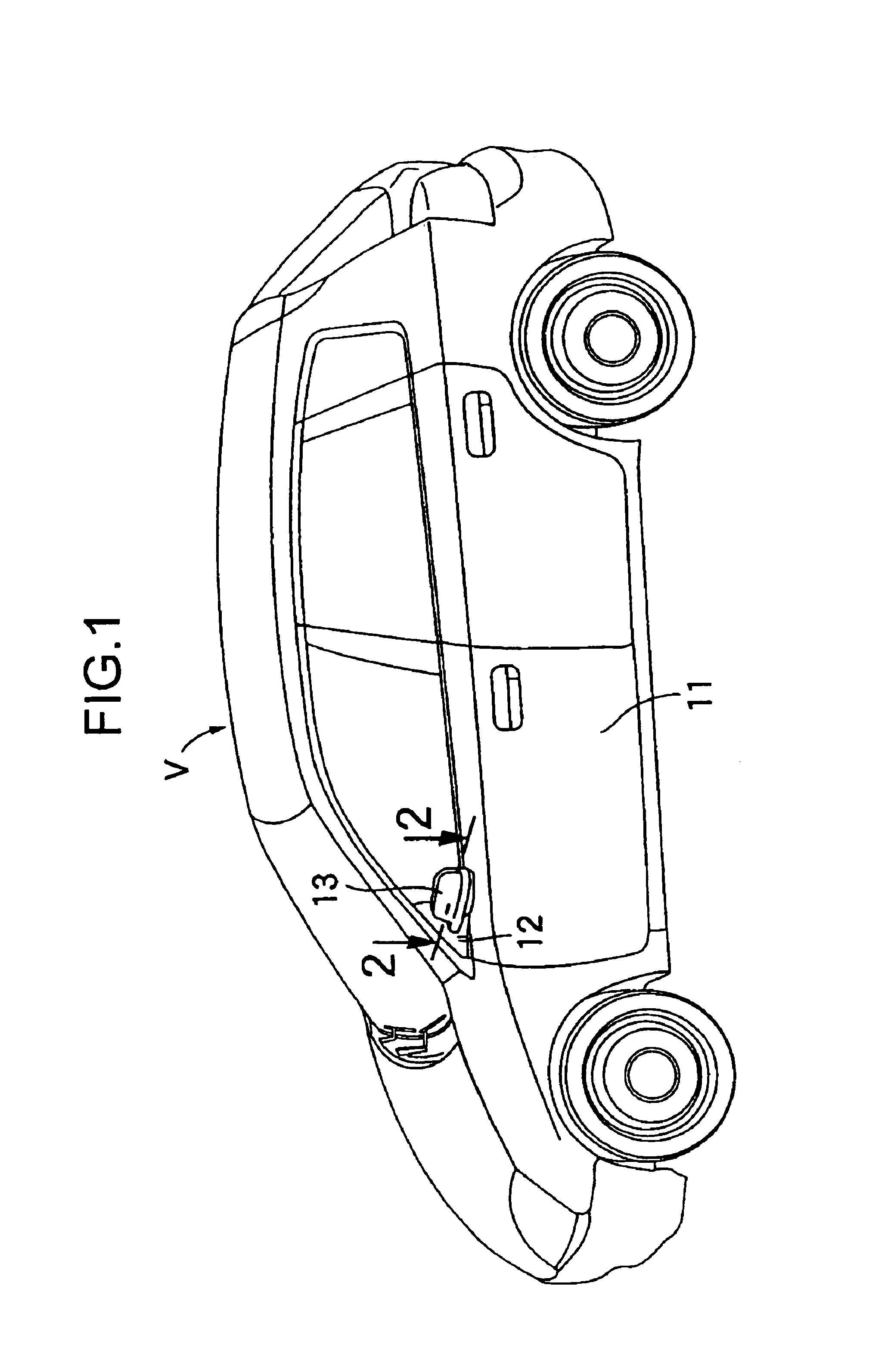
In FIG. 1, a base 12 is attached to a side door 11 of a passenger car V, and a mirror main portion 13 is rotationally supported on the base 12 such that it can rotate forward to backward of the passenger car V.

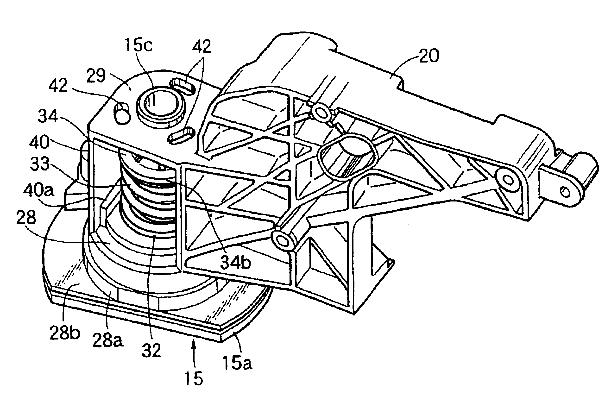
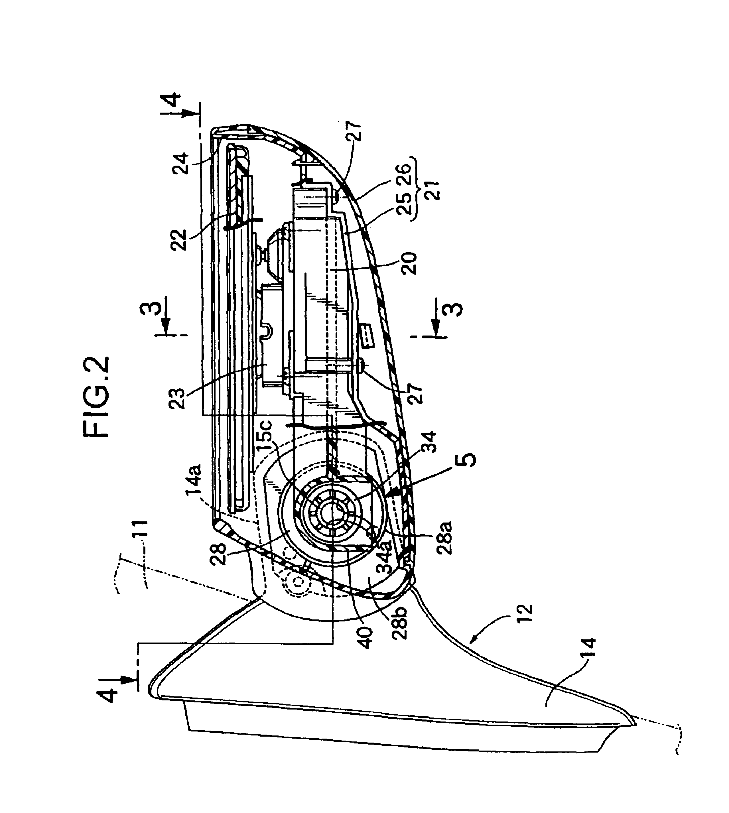
Referring to FIG. 1 to FIG. 4 together, the base 12 comprises a base member 14 made of a synthetic resin attached to the side door 11 and having a support arm 14a protruded outward of the side door 11, and a metal support member 15 attached to the base member 14.

An opening 16 is formed to an upper portion of the support arm 14a, and the support member 15 comprises a flat plate part 15a disposed to the opening 16 and forming a support seat 17 facing upward, a support cylinder 15b of a substantially closed cylindrical shape raised upward from the support seat 17 and a support shaft 15c of a cylindrical shape having a diameter smaller than that of the support cylinder 15b and raised upward from the central portion at a ...


PUM


Abstract

A door mirror including mirror-supporting therewith bracket supported by a bearing portion disposed integrally to a base of a support shaft, and a coil spring located under compression between a resilient receptacle and the bearing portion for urging the bearing portion toward the support seat. One bearing portion supported to the base end of the support and another bearing portion spaced apart from the bearing portion and supported rotationally on the top end of the support shaft are provided integrally to the bracket. The resilient receptacle is secured to a predetermined position of the support shaft so as to sandwich the coil spring that is compressed to a set load after passage of the support shaft through the coil spring located between both of the bearing portions between one of the bearing portions situated on the side of the support seat and the receptacle.

Description

BACKGROUND OF THE INVENTION1. Field of the InventionThe present invention concerns a door mirror for use in a vehicle including a base attached to a side door of the vehicle and having a support seat facing upward and a support shaft vertically disposed to the support seat, a bearing portion disposed integrally to a bracket for supporting a mirror and supported to the base of the support shaft while enabling the bracket to rotate in the forward and backward directions of the vehicle, and a coil spring located under compression between a resilient receptacle secured to the support shaft and the bearing portion for urging the bearing portion toward the support seat.2. Statement of the Related ArtThe door mirror of the structure described above has already been known, for example, in Japanese Utility Model Laid-Open No. 93231 / 1992 and Japanese Patent No. 3179337.By the way, between the support seat of the base and the bearing portion provided integrally to the bracket facing the suppor...

Claims


Application Information

Patent Timeline
Patent Type & Authority Patents(United States)
IPC IPC(8): B60R1/076B60R1/074
CPCB60R1/076
Inventor MURAKAMI, SHINICHI
Owner HONDA LOCK MFG CO LTD
Why Eureka
Try Eureka