Upright vacuum cleaner

Inactive Publication Date: 2013-04-04
DYSON TECH LTD
View PDF18 Cites 5 Cited by
  • Summary
  • Abstract
  • Description
  • Claims
  • Application Information

AI Technical Summary

Benefits of technology

[0020]This particular arrangement has the benefit that both the handle and wand are retractable for compact storage when the cleaner is not in use. The handle assembly and the wand are arranged so that the wand effectively extends and retracts in sympathy with the handle when it is being stored on the cleaner. This brings the additional benefit that when the handle is extended for use, the wand is likewise extended automatically; similarly, when the handle is returned to the compact storage position, the wand likewise

Problems solved by technology

It is usually completely impractical to use the main cleaner head for this purpose: the clea

Method used


Image

  • Upright vacuum cleaner
  • Upright vacuum cleaner
  • Upright vacuum cleaner

Examples


Embodiment Construction

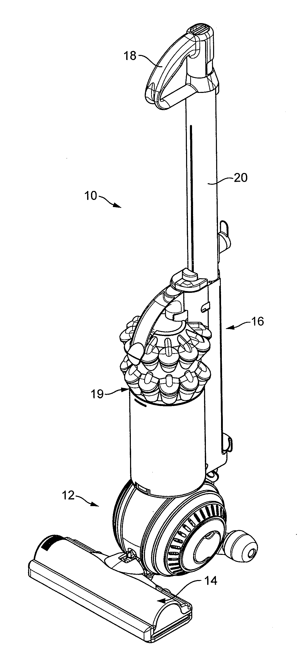
[0054]FIG. 3 shows an upright vacuum cleaner 10.

[0055]The cleaner 10 has a rolling head assembly 12 which carries a fixed cleaner head 14, and an ‘upright’ body 16 which can be reclined relative to the head assembly 12 and which includes a handle 18 for manouevring the cleaner 10 across the floor. In use, a user grasps the handle 18 and reclines the upright body 16 until the handle 18 is disposed at a convenient height for the user; the user can then roll the vacuum cleaner 10 across the floor using the handle 18 in order to pick up dust and other debris on the floor. The dust and debris is drawn in through a downward-facing suction inlet on the cleaner head 14 by a motor-driven fan housed on-board the cleaner 10. From here, the dirt-laden air stream is ducted in conventional manner under the fan-generated suction pressure to a cyclonic separating apparatus 19, where dirt is separated from the air before the relatively clean air is then expelled back to the atmosphere.

[0056]The hand...


PUM


Abstract

An upright vacuum cleaner comprising a telescopic suction wand fluidly connected to a separating apparatus on the cleaner via a hose and which is used, as required, to clean above the level of the floor. The wand comprises a lower wand section, an upper wand section telescopically mounted to the lower wand section and a moveable locking member which, when the wand is released for use, is biased towards a locking position for locking out the wand sections in telescopic extension. The locking member is releasable from this locking position via a reaction member provided on the cleaner, against which reaction member a user may readily force the biased locking member out of the locking position using the locked-out wand.

Description

REFERENCE TO RELATED APPLICATIONS[0001]This application claims the priority of United Kingdom Application No. 1116806.9 filed 29 Sep. 2011, the entire contents of which are incorporated herein by reference.FIELD OF INVENTION[0002]The present invention relates generally to upright vacuum cleaners, which includes dry, wet or “wet-and-dry” upright vacuum cleaners.BACKGROUND OF INVENTION[0003]Upright cleaners typically have a rolling head assembly, which carries a fixed cleaner head in plane-parallel contact with the floor surface. This head assembly is mounted on a reclining ‘upright’ body which carries a handle at its upper end. In the conventional floor-cleaning mode, a user reclines the ‘upright’ body until the handle is at a convenient height, and then uses the handle manually to push the cleaner across the floor, maintaining the cleaner head in plane parallel contact with the floor surface.[0004]It is often desirable to vacuum-clean above the level of a floor. For example, it may ...

Claims


Application Information

Patent Timeline
IPC IPC(8): A47L9/24
CPCA47L9/244A47L5/32A47L9/24
Inventor MCLUCKIE, PAUL ANDREWPARK, CHARLES EDWARDDYSON, JAMESGAMMACK, PETER DAVID
Owner DYSON TECH LTD
Why Eureka
Try Eureka