Display device

a display device and display part technology, applied in the field of display devices, can solve the problems of troublesome lens focus, difficult to display bright images on the screen, and inability to meet the needs of people, etc., and achieve the effect of facilitating the setting up of the display device, reducing the swaying of the display part, and preventing the sag of the display par

Inactive Publication Date: 2009-07-14
PANASONIC CORP
View PDF19 Cites 37 Cited by
  • Summary
  • Abstract
  • Description
  • Claims
  • Application Information

AI Technical Summary

Benefits of technology

[0021]This structure enables the holding part to be stretched across the rear surface of the display part when the display part is spread out, thereby reducing the swaying, sagging, or wrinkling of the display part.
[0036]Thus the present invention can reduce the swaying of the display part caused by wind and other factors, while maintaining the desirable feature i.e. compact storage of the roll-up sheet-like display device using a self-luminous element such as an organic EL element. The invention can also prevent the display part from being sagged, thereby facilitating the setting up of the display device.

Problems solved by technology

It is not practical, however, to install displays above a certain size in houses, assembly halls, conference rooms and the like because this hinders the use of these spaces for other purposes.
Projectors, however, have a disadvantage that it is difficult to display bright images on the screen.
As another disadvantage, it is troublesome to focus the lens every time they are set up.
However, when a display device using a self-luminous element such as an organic EL display with a large screen above a certain size like 100 in or more is designed to be rolled up, the high flexibility causes the following problems when the screen is set up.
For one thing, when a sheet-like large image display device using an organic EL is set up, the image display part is swayed by the wind from an air conditioner or shaken by vibration from the acoustic device such as a speaker, making it harder to provide clear images.
For another thing, it is difficult to property set up the display device itself.
This means that the swaying of the screen directly leads to difficulty in displaying clear images.
This may be highly likely to cause trouble when the display part sways and hits a wall or a stationary object around it, or sags and bends to damage pixels while being set up.
Therefore, the swaying of the display device may cause the distribution cable connected with the external devices to be yanked, thereby pulling the wiring out or causing the external devices yanked along with the distribution cable to fall off the shelf.
However, in a lightweight and flexible sheet-like image display device using a self-luminous element such as an organic EL element, the aforementioned problem cannot be fully solved only by the mechanism of stretching the display fixing frames to the display ends.
More specifically, the mere provision of the display fixing frames on the ends of the display cannot sufficiently reduce vibration or sagging at the center of the display part that is not supported by the display fixing frames.

Method used


Image

  • Display device
  • Display device
  • Display device

Examples


first exemplary embodiment

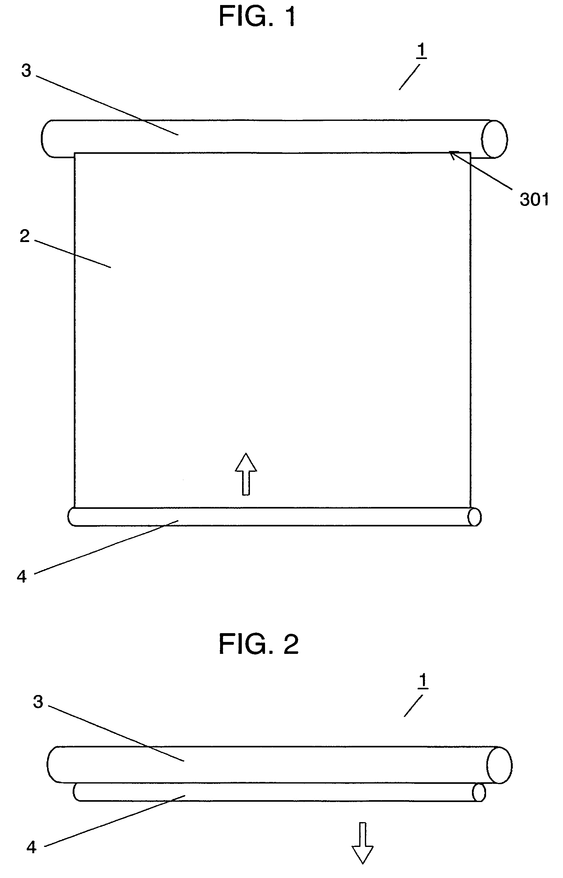
[0101]FIGS. 1 and 2 are views showing a structure of display device 1 of a first embodiment of the present invention. FIG. 1 shows a state in which roll-up sheet-like display part 2 using an organic EL element is rolled out from cylindrical take-up part 3. FIG. 2 shows a state in which display part 2 is rolled up for storage in take-up part 3.

[0102]When display part 2 is housed in take-up part 3 (FIG. 2), the user of display device 1 can pull bar-shaped pulling part 4 attached at the bottom of display part 2 downward (in the arrow direction) to spread display part 2 out as shown in FIG. 1. On the contrary, when display part 2 is in a spread state (FIG. 1), the user can push pulling part 4 upward (in the arrow direction) to roll up display part 2 inside take-up part 3 as shown in FIG. 2.

[0103]Thus housing display part 2 completely in take-up part 3 allows a large-screen image display device to be stored compactly and to be ultraportable. It also prevents display part 2, which is not ...

second exemplary embodiment

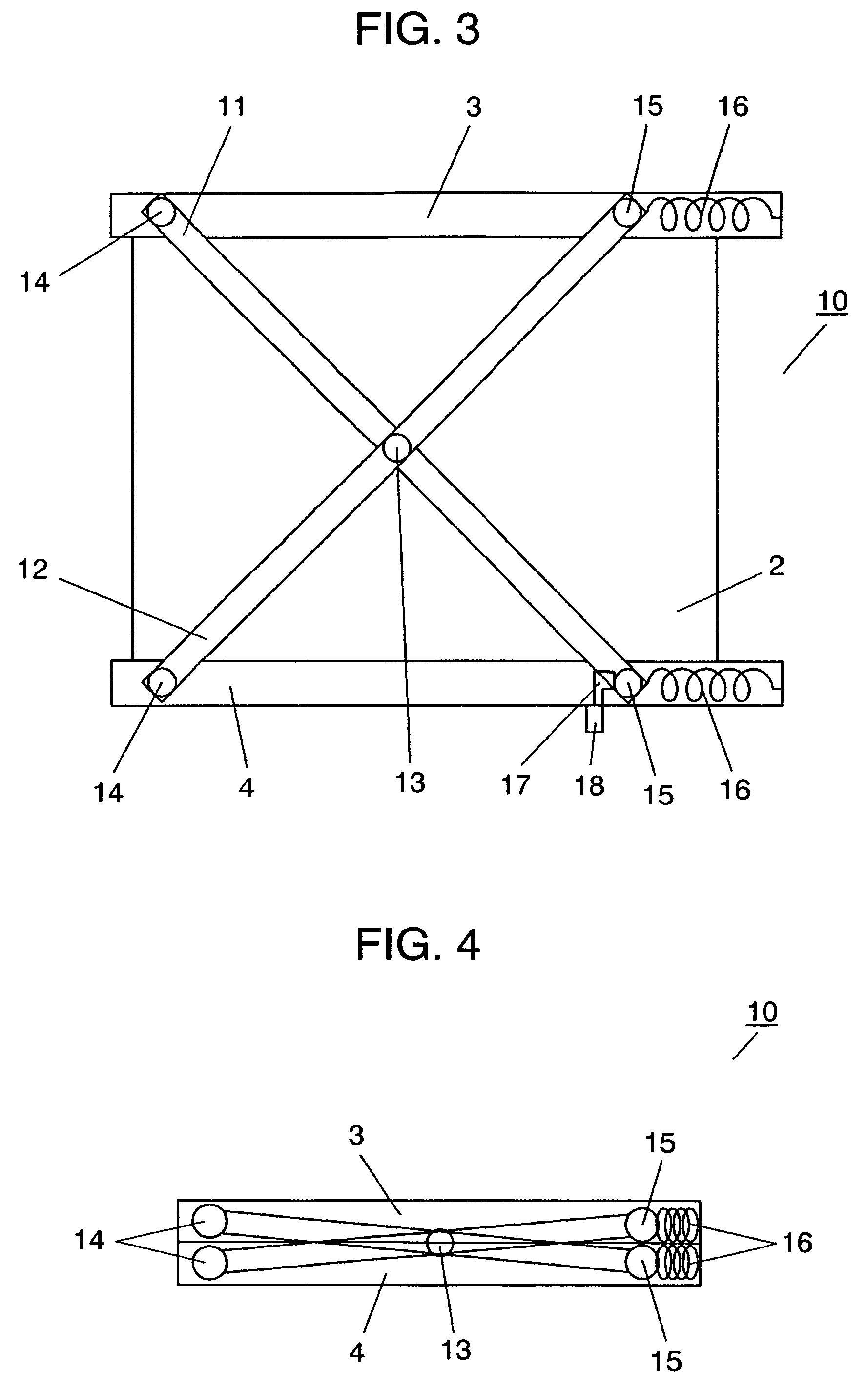
[0109]FIGS. 3 and 4 are rear views showing a structure of display device 10 of a second embodiment of the present invention. FIG. 3 shows a case in which roll-up sheet-like display part 2 using an organic EL element in display device 10 is spread out. FIG. 4 shows a case in which display part 2 is rolled up for storage in cylindrical take-up part 3.

[0110]In FIG. 3, display part 2 is provided on its rear surface with a set of linkage consisting of first rail 11 and second rail 12, which is rotatably supported at rail intersection 13. Take-up part 3 and cylindrical pulling part 4 have a pair of first rail supports 14 supporting one end of first and second rails 11 and 12 rotatably, and a pair of second rail supports 15 supporting the other end of first and second rails 11 and 12 rotatably and slidably. Second rail supports 15 are biased toward one end of take-up part 3 and pulling part 4 by springs 16 provided on the one end of take-up part 3 and pulling part 4. Springs 16 are extende...

third exemplary embodiment

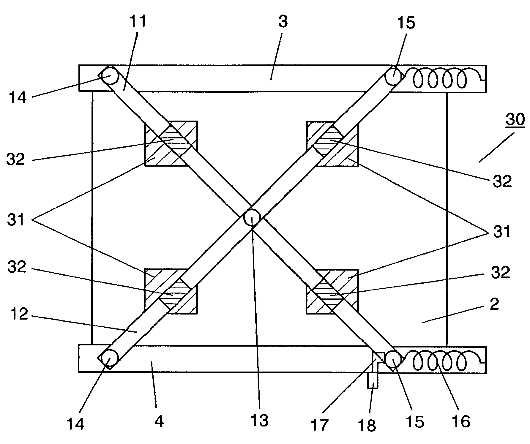
[0127]FIG. 9 is a rear view showing a structure of display device 30 of a third embodiment of the present invention. FIG. 9 shows a state in which roll-up sheet-like display part 2 using an organic EL element is rolled out from cylindrical take-up part 3. Display part 2 is provided on its rear surface with sheet-like first magnets 31, which can be rolled up together with display part 2. The rear surface is further provided with a set of linkage consisting of first rail 11 and second rail 12, which is pasted with second magnets 32 corresponding in position to first magnets 31. When display part 2 is rolled out from take-up part 3 completely as shown in FIG. 9, first magnets 31 and second magnets 32 are coupled magnetically.

[0128]To roll up display part 2 inside take-up part 3 for storage, the user can release the coupling between first magnets 31 and second magnets 32 and then operate switch 18 to disengage stopper 17. As a result, the restoring force of springs 16 causes second rail...


PUM


Abstract

A display device includes a display part made of a roll-up sheet-like direct-view display element; a take-up part attached on one end of the display part, the take-up part allowing the display part to be rolled up; a pulling part attached on the other end of the display part, the pulling part allowing the display part to be roll out; and a holding part for holding the display part from behind. The holding part is formed of linkage, which can be stored on the rear surface of the display part when the display part is rolled up, and can be stretched across the rear surface of the display part when the display part is rolled out. This enables the holding part to be stretched across the rear surface of the display part when the display part is spread out so as to prevent the display part from swaying, thereby maintaining excellent display.

Description

[0001]This application is a U.S. National Phase Application of PCT International Application No. PCT / JP2005 / 002867, filed Feb. 23, 2005.TECHNICAL FIELD[0002]The present invention relates to a display device, and more particularly, to a display device having a display part that can be rolled up and is sheet-like in form.BACKGROUND ART[0003]In recent years, there is a rapidly increasing demand for large flat screen displays. To meet this demand, there have been efforts to increase the screen size of plasma displays, liquid crystal displays and organic EL displays.[0004]It is not practical, however, to install displays above a certain size in houses, assembly halls, conference rooms and the like because this hinders the use of these spaces for other purposes.[0005]For this reason, in order to watch DVDs or Blue-ray Discs on a large screen above a certain size or to output data from PC screens, projection display devices such as projectors are often used. Projectors are compact enough t...

Claims


Application Information

Patent Timeline
Patent Type & Authority Patents(United States)
IPC IPC(8): G09F11/18H01L51/50G03B21/58G09F9/00G09F9/33H05B33/14
CPCG03B21/58G09F9/301G09F9/33G09F9/00H05B33/14
Inventor OFUJI, MASAAKITAKI, NAOYA
Owner PANASONIC CORP
Why Eureka
Try Eureka