Camera module

Inactive Publication Date: 2010-04-08
FUJIFILM CORP
View PDF16 Cites 45 Cited by
  • Summary
  • Abstract
  • Description
  • Claims
  • Application Information

AI Technical Summary

Benefits of technology

[0014]According to the present invention, the positioning members are provided in the held members formed on the top and bottom or both lateral surfaces of the

Problems solved by technology

If the camera module is further downsized, however, the image capturing window and the terminal group will occupy a large part of the module.

Method used


Image

  • Camera module
  • Camera module
  • Camera module

Examples


Embodiment Construction

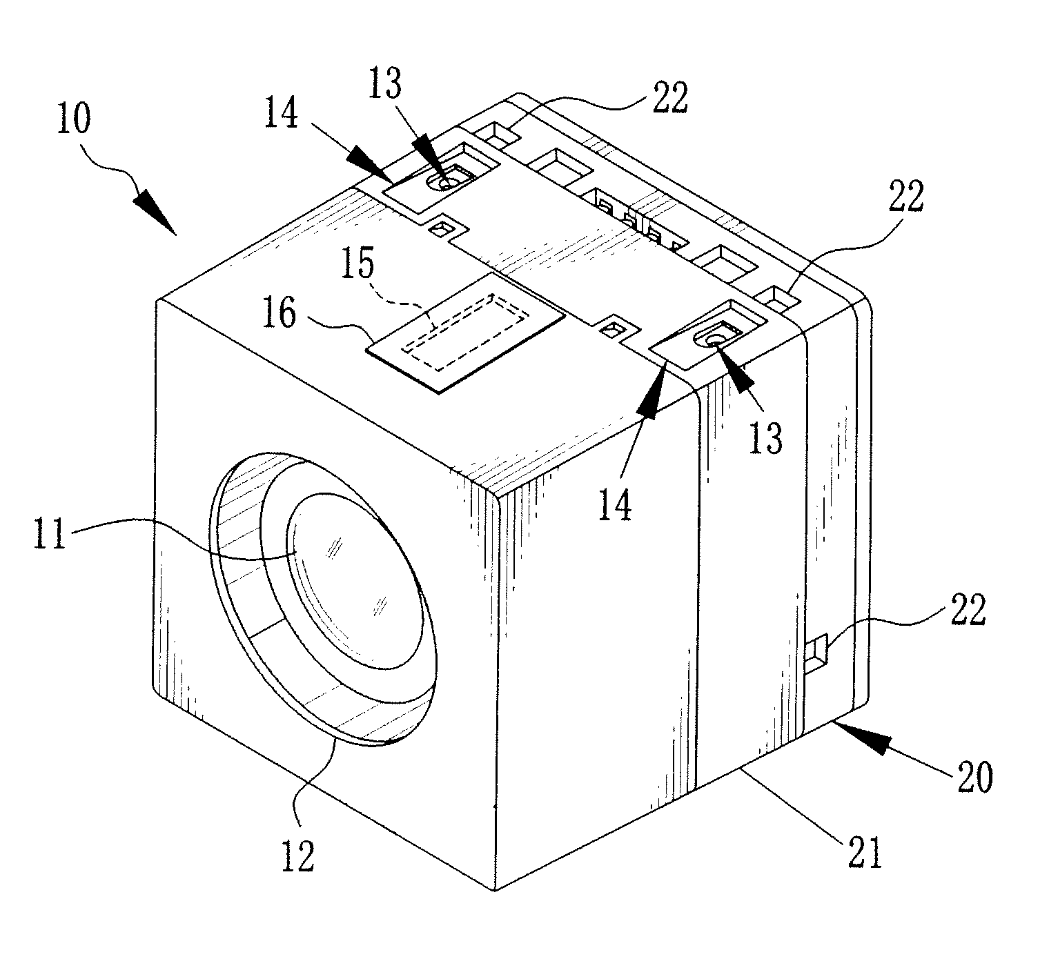
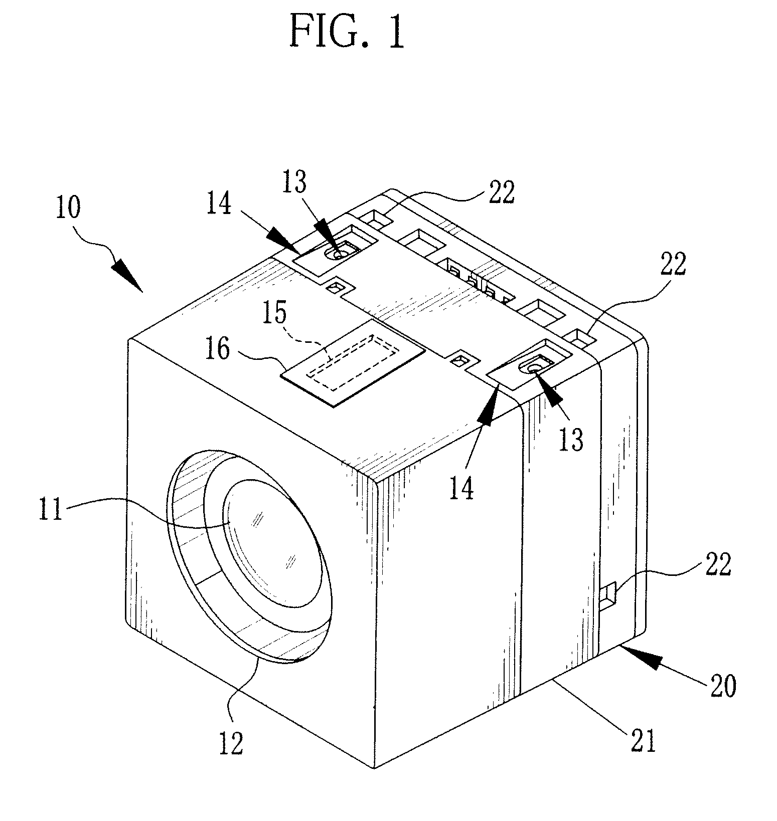
[0031]Referring to FIG. 1, a camera module 10 has a cubic shape of about 6-10 mm cube, designed for installation in mobile camera phones and such electronic devices. The camera module 10 has an image capturing window 12 on the front surface for exposing a taking lens 11, and pairs of held members (receiving portions) 14 each having a positioning member 13 on the top and bottom surfaces. Also on the top surface is formed an opening 15 for inserting a probe of an assembly machine, and this opening 15 is covered by a plate 16 after assembly.

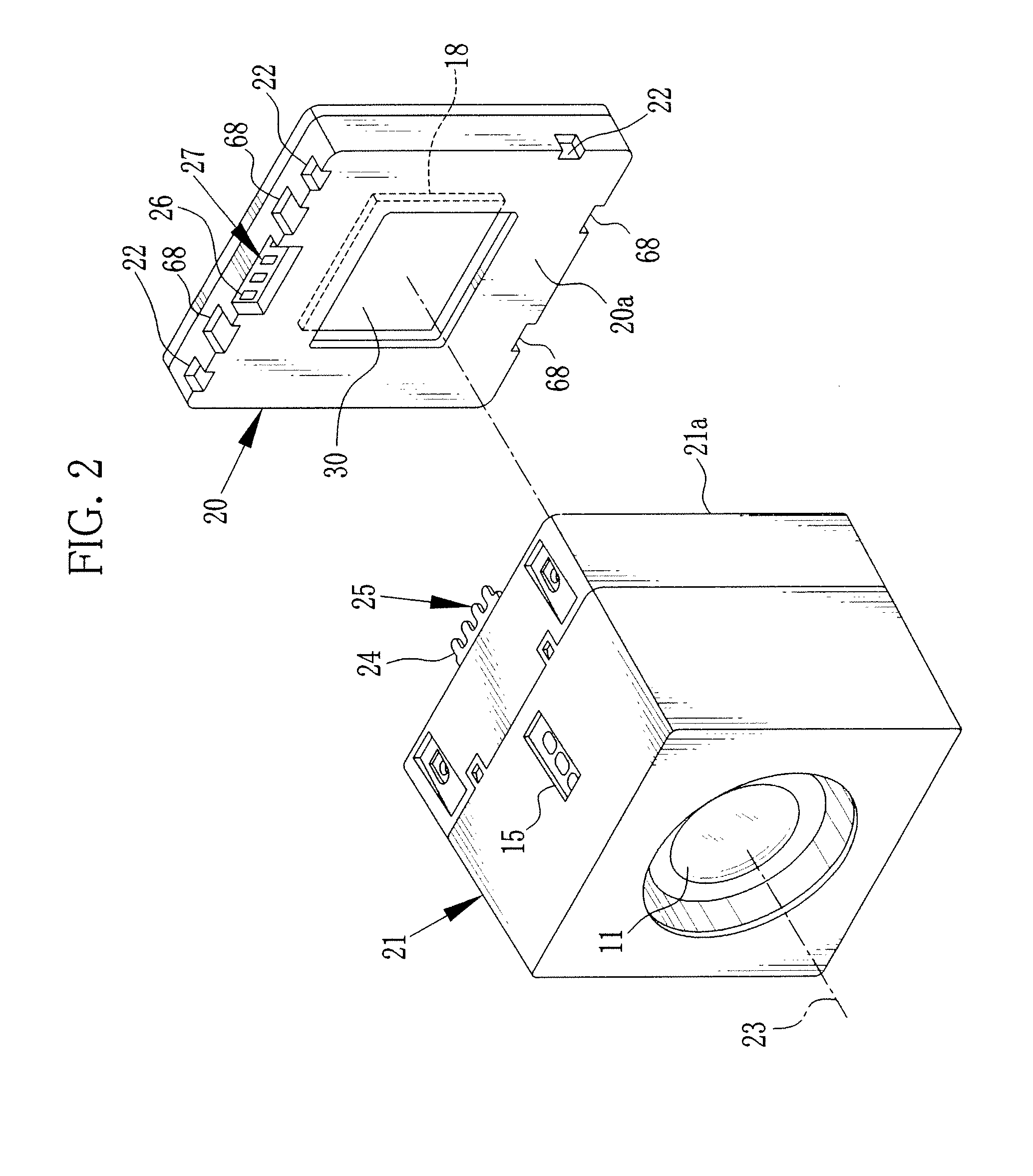
[0032]As shown in FIG. 2, the camera module 10 includes a sensor unit 20 and a lens unit 21. The sensor unit 20 is positioned in such a manner that its imaging plane is orthogonal to an imaging optical axis 23 (the optical axis of the taking lens 11), and then fixed to the lens unit 21. More specifically, two mating surfaces 20a, 21a of the sensor unit 20 and the lens unit 21 are joined by firstly applying an ultraviolet (UV) curable adhesive resin ...


PUM


Abstract

A camera module has a sensor unit holding an image sensor and a lens unit holding a taking lens. The sensor unit and the lens unit are joined in such a manner that an imaging plane of the image sensor is orthogonal to an optical axis of the taking lens. Each of top and bottom surfaces of the lens unit has a pair of held members to be held by holding jigs. This held member is a depression of triangular cross section defined by a bottom face that inclines toward rear surface of the lens unit. Each held member contains a positioning member that receives a pin jig when the position and angle of the sensor unit is adjusted relative to the lens unit.

Description

FIELD OF THE INVENTION[0001]The present invention relates to a camera module made up of a sensor unit holding an image sensor and a lens unit holding a taking lens.BACKGROUND OF THE INVENTION[0002]A camera module is an integration of a lens unit holding a taking lens and a sensor unit holding an image sensor, such as a CCD or CMOS. A typical camera module is small enough to fit in the casings of mobile phones and door phones.[0003]Earlier camera modules are generally equipped with low-resolution image sensors of no more than 1-2 million pixels. Having a large aperture ratio, this type of low-resolution image sensor does not require precise positioning between the taking lens and the image sensor to produce an image with resolution equivalent to the number of pixels.[0004]Current camera modules, in contrast, employ a larger number of pixels, as with normal digital cameras, and even have high-resolution image sensors of up to 3-5 million pixels. The high-resolution image sensors have ...

Claims


Application Information

Patent Timeline
IPC IPC(8): H04N5/225
CPCH04N5/2251H04N5/2257H04N5/2253H04N23/50H04N23/57H04N23/54H04N23/00
Inventor MORITA, MASAYA
Owner FUJIFILM CORP
Why Eureka
Try Eureka