

Relay connection unit for vehicle
- Summary
- Abstract
- Description
- Claims
- Application Information
AI Technical Summary
Benefits of technology
Problems solved by technology
Method used
Image

Examples
first embodiment
[0067]FIGS. 1 through 8 show the present invention.
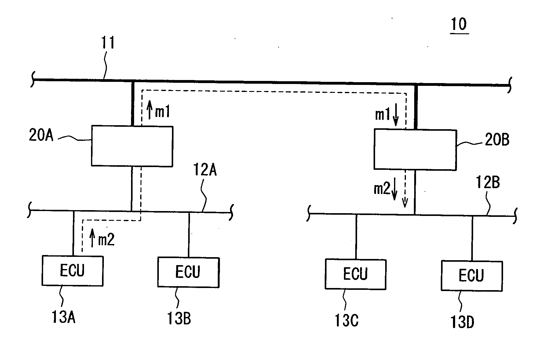
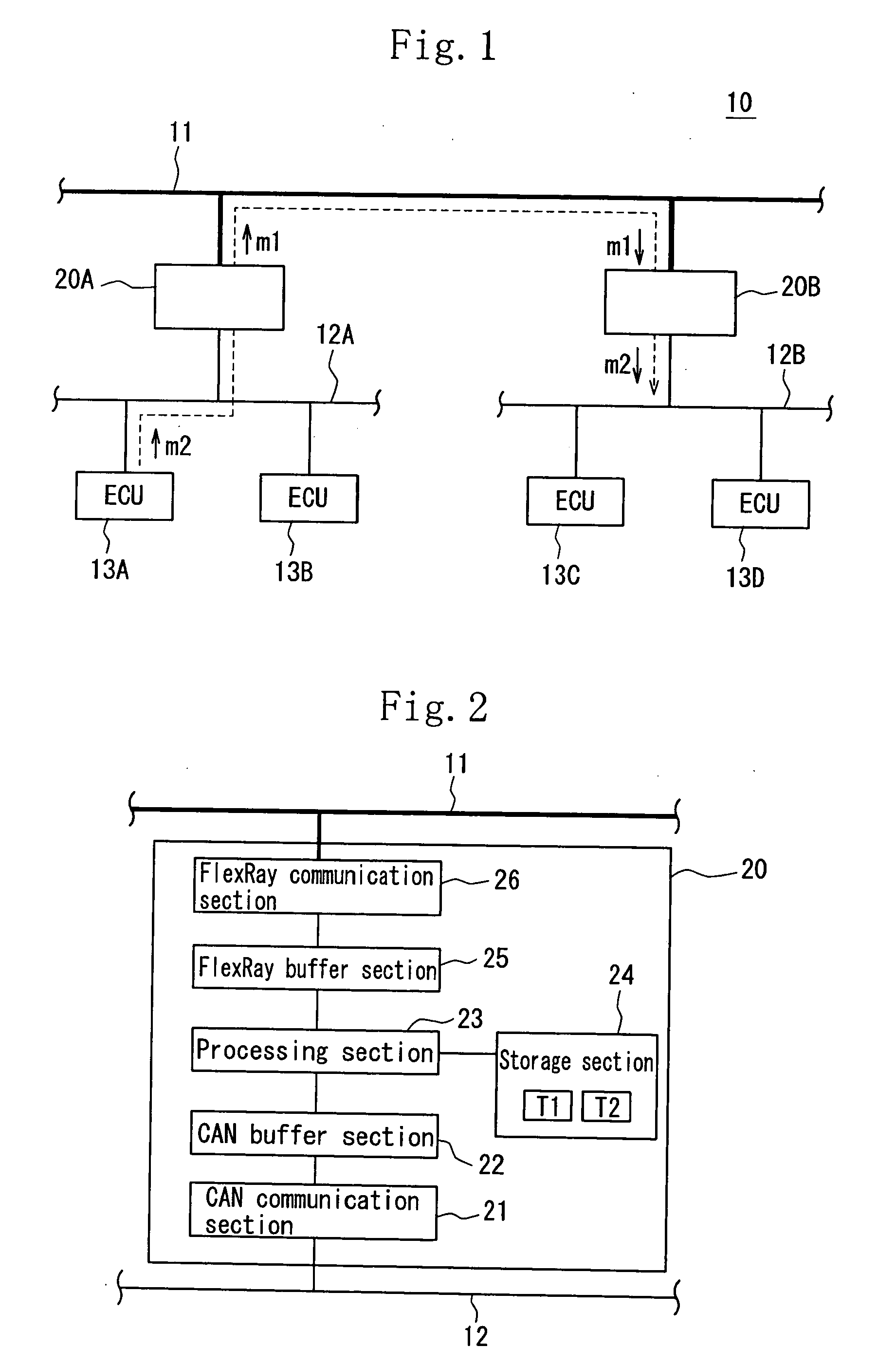
[0068]In the first embodiment, a relay connection unit 20(20A, 20B) of the present invention is connected to a FlexRay communication line 11 consisting of a first communication line shown with a thick line in FIG. 1, and a plurality of ECUs 13 (ECUs 13A and 13B are connected to relay connection unit 20A, and ECUs 13C and 13D are connected to relay connection unit 20B) is connected to each relay connection unit 20 via a CAN communication line 12(12A,12B) consisting of a second communication line to construct a LAN 10 mounted on a vehicle.
[0069]In the LAN 10 mounted on the vehicle, when a message is sent and received between the ECU 13A connected to the relay connection unit 20A and the ECU 13C connected to the relay connection unit 20B, the message is sent from the ECU 13A to the relay connection unit 20A via the CAN communication line 12A, sent from the relay connection unit 20A to the relay connection unit 20B via the FlexRay commu...
PUM
 Abstract
Description
Claims
Application Information